Magnetic measurement system

A measurement and magnetic field technology, which is applied in the field of magnetic measurement system, can solve the problems that the data is prone to errors and the magnetic field cannot be measured with good accuracy.

Inactive Publication Date: 2016-11-30
SEIKO EPSON CORP
View PDF1 Cites 4 Cited by
  • Summary
  • Abstract
  • Description
  • Claims
  • Application Information

AI Technical Summary

Problems solved by technology

Therefore, errors are likely to occur in the data obtained as the ambient magnetic field at the position of the pickup coil, and it may not be possible to accurately measure the magnetic field emitted by the living body.

Method used


Image

  • Magnetic measurement system
  • Magnetic measurement system
  • Magnetic measurement system

Examples


no. 1 approach

[0117]

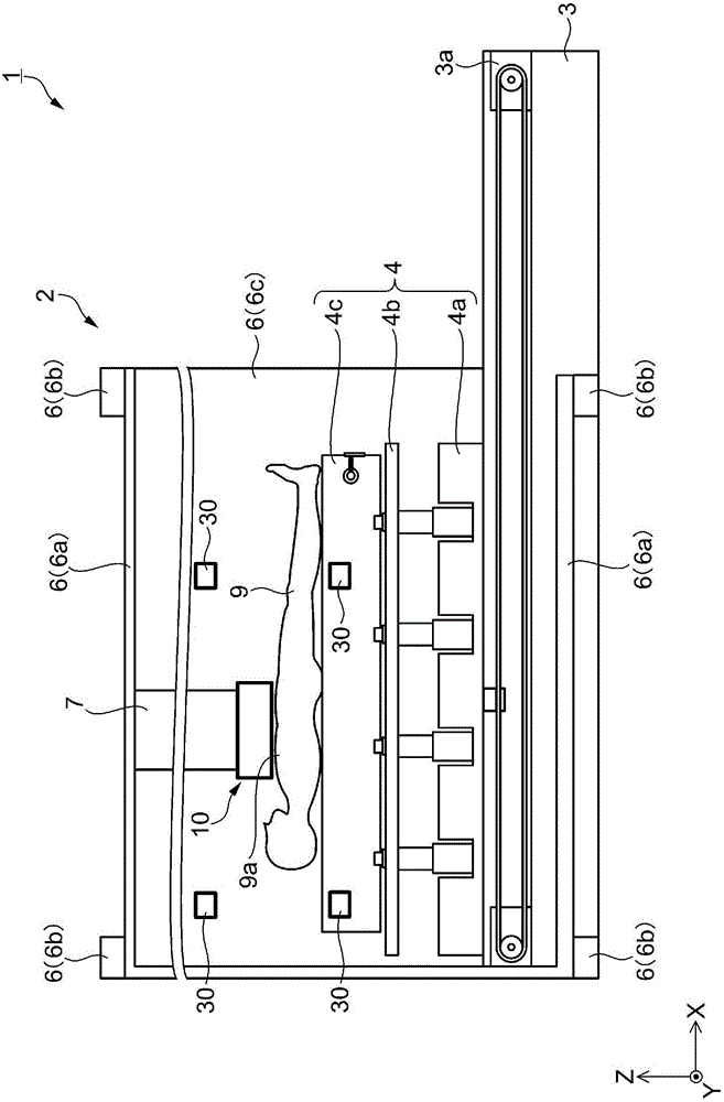
[0118] First, a configuration example of the magnetic measurement system according to the first embodiment will be described. figure 1 It is a schematic side view showing the configuration of an example of the magnetic measurement system according to the first embodiment. figure 1 The illustrated magnetic measurement system 1 is a system for measuring the cardiac magnetic field emitted from the heart of a subject (living body) 9 as a measurement target. Such as figure 1 As shown, the magnetic measurement system 1 includes a magnetic heart sensor 10 as a first magnetic sensor, a noise magnetic sensor 30 as a second magnetic sensor, and a magnetic measurement device 2 as a processing device.

[0119] The magnetic sensor 10 is a sensor for measuring a weak first magnetic field such as magnetism and brain magnetism, and a second magnetic field such as an external magnetic field (magnetic noise). Wait and use. The noise magnetic sensor 30 is a sensor that measures a s...

Embodiment 1-1

[0242] Figure 4 with Figure 5 It is an explanatory diagram of the arrangement of the noise magnetic sensor according to the embodiment 1-1. In detail, Figure 4 (a) is a stereogram, Figure 4 (b) is from Figure 4 A plan view viewed from the +X direction side of (a). Figure 5 (a) is from Figure 4 A plan view viewed from the +Y direction side of (a), Figure 5 (b) is from Figure 4 (a) A plan view viewed from the +Z direction side.

[0243] exist Figure 4 with Figure 5 Among them, in order to identify the eight noise magnetic sensors 30 individually, the first to eighth are called noise magnetic sensors 31 , 32 , 33 , 34 , 35 , 36 , 37 , and 38 , respectively. Moreover, when collectively referring to the above-mentioned noise magnetic sensors 31 , 32 , 33 , 34 , 35 , 36 , 37 , and 38 , they are called noise magnetic sensors 30 .

[0244] In the magnetic measuring system 1, four sensors of noise magnetic sensors 31, 33, 36, and 38 are attached to the main body 6...

Embodiment 1-2

[0261] In embodiment 1-2, since the positional relationship between the eight noise magnetic sensors 30 and the magnetic sensor 10 is the same as in embodiment 1-1, the illustration is omitted, and the most preferred cuboid 30a is L 1 =L 2 =L 3 = cuboid 30a of L. That is, the rectangular parallelepiped 30a is a cube whose one side has a length of 2L. The position vector r of the noise magnetic sensor 30 arranged at each vertex of such a cube whose length on one side is 2L k (magnetic sensor position r k ) is represented by Mathematical Formula 41.

[0262] [mathematical formula 41]

[0263]

[0264] When eight noise magnetic sensors 30 are arranged in this way, the magnetic sensor term matrix P (third matrix P) is represented by 1, L, and -L as shown in Mathematical Expression 42, and the calculation becomes simple.

[0265] [mathematical formula 42]

[0266] P = 1 1 ...


PUM


Abstract

The invention provides a magnetic measurement system capable of measuring the magnetic field of the measured target with high accuracy even in a case where an external magnetic field stronger than a weak magnetic field of a measured target is present. A magnetic measurement system (1) includes a heart magnetic field sensor (10) that measures a first magnetic field and a second magnetic field, a noise magnetic sensor (30) that measures the second magnetic field, and a magnetic measurement apparatus (2) that computes an approximate value of the second magnetic field in the heart magnetic field sensor (10) by using a measurement value in the noise magnetic sensor (30) and a multi-variable polynomial. The magnetic measurement apparatus (2) subtracts the approximate value of the second magnetic field from a measurement value in the heart magnetic field sensor (10).

Description

technical field [0001] The present invention relates to a magnetic measurement system. Background technique [0002] There has been proposed a magnetic measuring device for measuring the magnetic field of the heart, the magnetic field of the brain, etc. which are weaker than the earth's magnetism (for example, refer to Patent Document 1). The magnetic measurement device is non-invasive, and can measure the state of an organ without applying a load to a subject (living body). Patent Document 1 discloses a living body magnetism measurement device having a sensor (pickup coil) for measuring a magnetic field emitted by a living body and a sensor (reference coil) for measuring an ambient magnetic field as noise. The ambient magnetic field (noise) contained in the magnetic field measured by the pickup coil is removed based on the ambient magnetic field measured by the reference coil. [0003] In the biological magnetism measurement device described in Patent Document 1, the numb...

Claims


Application Information

Patent Timeline
Patent Type & Authority Applications(China)
IPC IPC(8): A61B5/04A61B5/00G01R33/032
CPCA61B5/4064A61B5/72A61B5/7235A61B5/242A61B5/243A61B5/245G01R33/032A61B5/0044A61B5/7214A61B2562/0223A61B2562/04A61B2576/023G01R33/0023G01R33/028G16H30/40
Inventor 长坂公夫宫坂光敏
Owner SEIKO EPSON CORP
Why Eureka
Try Eureka