Adhesive device for display

A technology for bonding devices and displays, applied to lamination devices, instruments, chemical instruments and methods, etc., can solve the problems of reducing the adsorption area of ​​the upper electrostatic chuck 60, reducing the adsorption area of ​​the upper suction cup 60, and reducing the adsorption force, etc. Achieve the effect of shortening the vacuum formation time and shortening the process takt time

Inactive Publication Date: 2018-06-15
DAS CO LTD
View PDF4 Cites 0 Cited by
  • Summary
  • Abstract
  • Description
  • Claims
  • Application Information

AI Technical Summary

Problems solved by technology

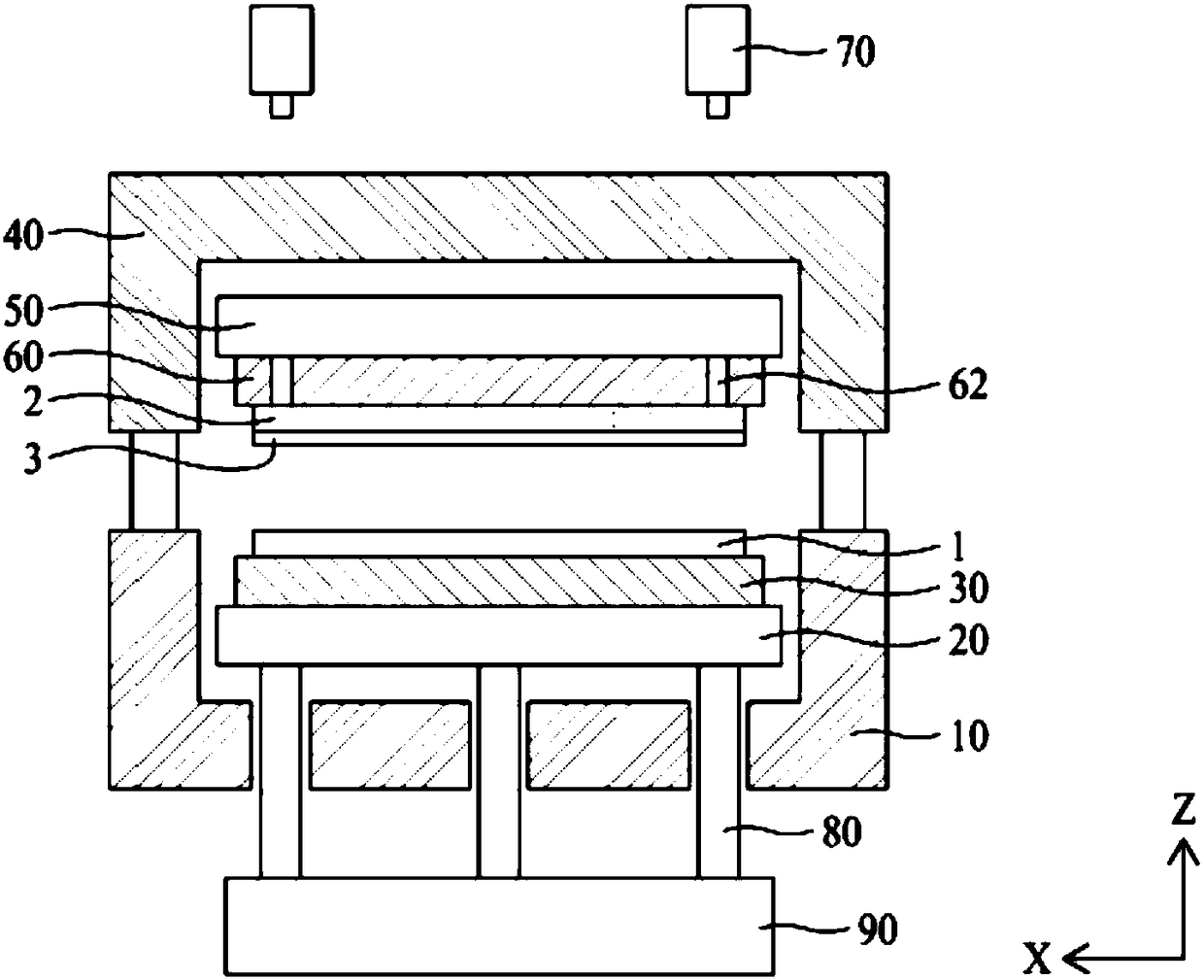
[0013] First, since the alignment marks arranged on the display panel 1 and the transparent cover 2 are photographed by the vision camera 70 disposed on the upper electrostatic chuck 60, the observation hole disposed on the upper electrostatic chuck 60 for photographing by the vision camera 70 will The adsorption area of ​​the upper suction cup 60 is reduced, and the transparent cover 2 may fall due to the reduction of the adsorption force of the upper electrostatic chuck 60
In particular, the upper electrostatic chuck 60 can further reduce the adsorption area of ​​the upper electrostatic chuck 60 by arranging an observation hole area with observation holes for each sample in order to be able to cope with various samples.
[0014] Second, the electrostatic chucks 30 and 50 are used to support the display panel 1 and the transparent cover 2 respectively, and thus the adsorption force is low and the structure is complicated
[0015] Third, in the interval space between the driving shaft 80 and the lower chamber 10, the positions of the display panel 1 and the transparent cover 2 are aligned by the movement of the lower platform 20, so that the inside of the lower chamber 10 for forming a vacuum environment The volume is structurally large, so the time for creating a vacuum increases, which in turn increases the process generation tact time (tact time)

Method used


Image

  • Adhesive device for display
  • Adhesive device for display
  • Adhesive device for display

Examples


Embodiment Construction

[0046]The meanings of the terms described in this specification should be understood as follows.

[0047] As for a singular expression, as long as it is not defined differently in the article, it should be understood as including a plurality of expressions. Words such as "first" and "second" are used to distinguish one constituent element from other constituent elements, so the scope of rights shall not be limited by such terms. Words such as "comprising" or "having" shall not be interpreted as the existence or possibility of addition of one or more other features or numbers, steps, actions, constituent elements, parts or combinations. The term "at least one" should be interpreted to include all combinations that can be revealed from more than one of the associated items. For example, "at least one of the first item, the second item, and the third item" means not only each of the first item, the second item, or the third item, but also from the first item, the second item, an...


PUM


Abstract

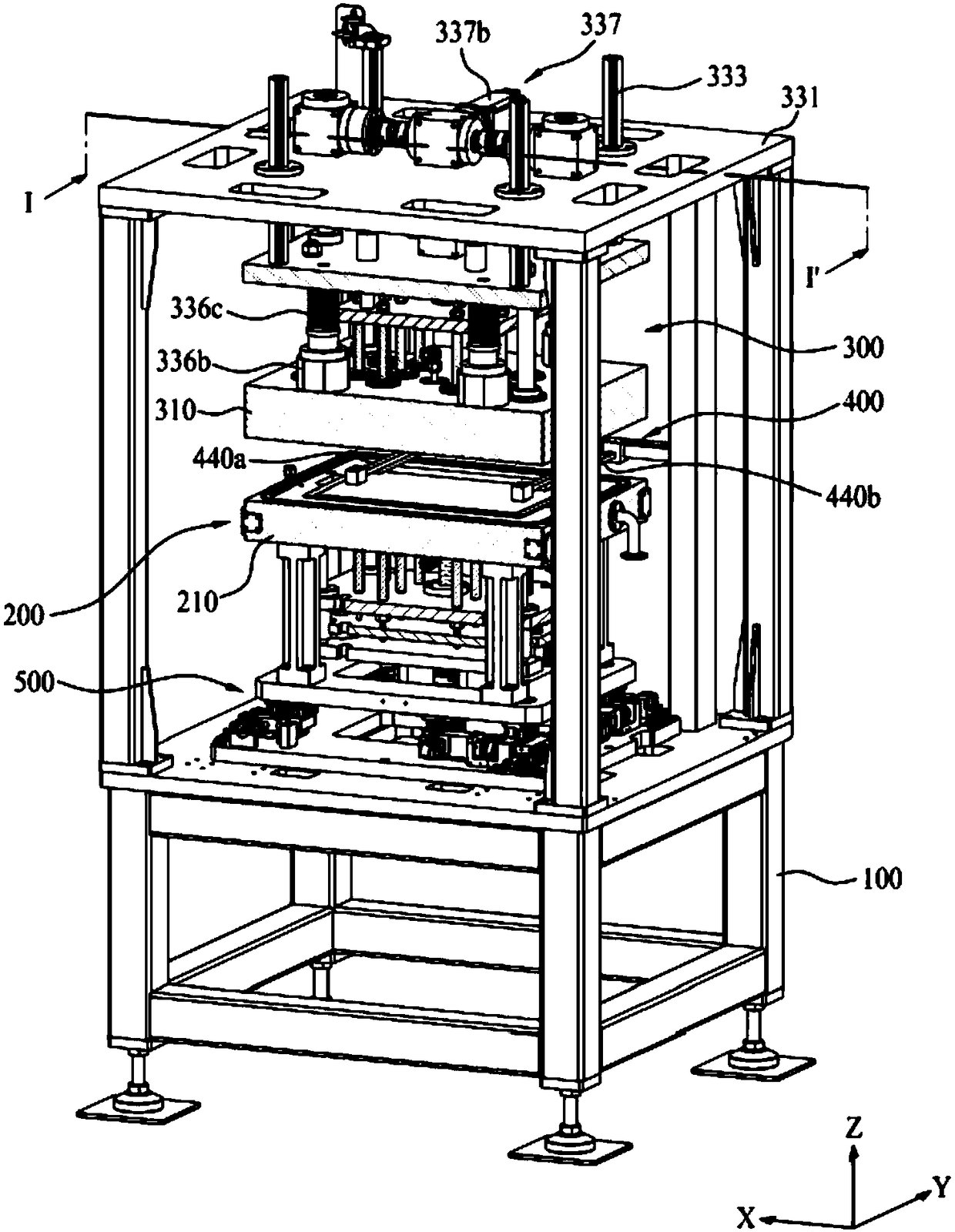
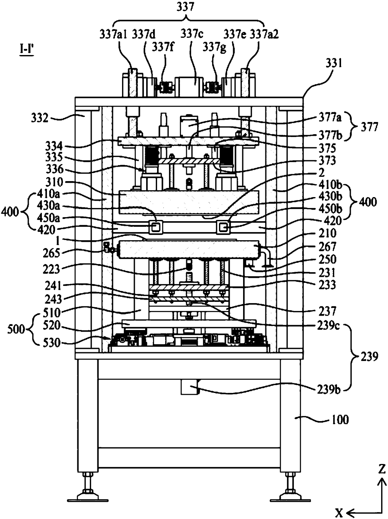
An objective of the present invention is to provide a bonding device for a display capable of aligning a position of a display panel with that of a transparent cover without degrading a bonding property toward a target. The bonding device for a display according to the present invention can comprise: a lower chamber module supporting the display panel; a an upper chamber module supporting the transparent cover; a camera module which takes an image of a panel alignment mark provided on a display panel and a cover alignment mark provided on a transparent cover between a lower chamber module supporting the display panel and an upper chamber module supporting the transparent cover; and an aligning module which aligns a position of the panel alignment mark with that of the cover alignment mark based on the image taken by the camera module. According to the present invention, a volume of a bonding space for bonding the display panel with the transparent cover is minimized, and a vacuum forming time is decreased. Therefore, it is possible to decrease a tact time of a bonding process.

Description

technical field [0001] The present invention relates to a bonding device for a display, and more specifically relates to a bonding device for a display for bonding a display panel and a transparent cover. Background technique [0002] Recently, flat panel display devices are being developed and commercialized while the display industry is rapidly developing in the semiconductor industry. Here, the flat panel display device includes a liquid crystal display device, a plasma display device, an organic light emitting display device, an electrophoretic display device, an electrowetting display device, and the like. Among such flat-panel display devices, liquid crystal display devices and organic light-emitting display devices are widely used in display devices of portable electronic devices such as notebook computers, tablet computers, smart phones, and smart watches, in addition to televisions or monitors. [0003] In a portable electronic device equipped with a display device...

Claims


Application Information

Patent Timeline
Patent Type & Authority Patents(China)
IPC IPC(8): B32B37/00G02F1/13
CPCB32B37/0046G02F1/1303
Inventor 郑钟范韩庆俊徐汉基郑富永
Owner DAS CO LTD
Why Eureka
Try Eureka