High-performance tool cooling system

A tool and coolant technology, applied in forming tools, manufacturing tools, metal processing equipment, etc., can solve problems such as increasing the use of lubricants, reducing the life of mold tools, and prolonging the cycle

Inactive Publication Date: 2016-11-30
格鲁帕铸造有限责任公司
View PDF2 Cites 5 Cited by
  • Summary
  • Abstract
  • Description
  • Claims
  • Application Information

AI Technical Summary

Problems solved by technology

This can prolong cycle times, increase lubricant usage, increase fluid recovery costs, and reduce mold tool life due to tool steel failure

Method used


Image

  • High-performance tool cooling system
  • High-performance tool cooling system
  • High-performance tool cooling system

Examples


Embodiment Construction

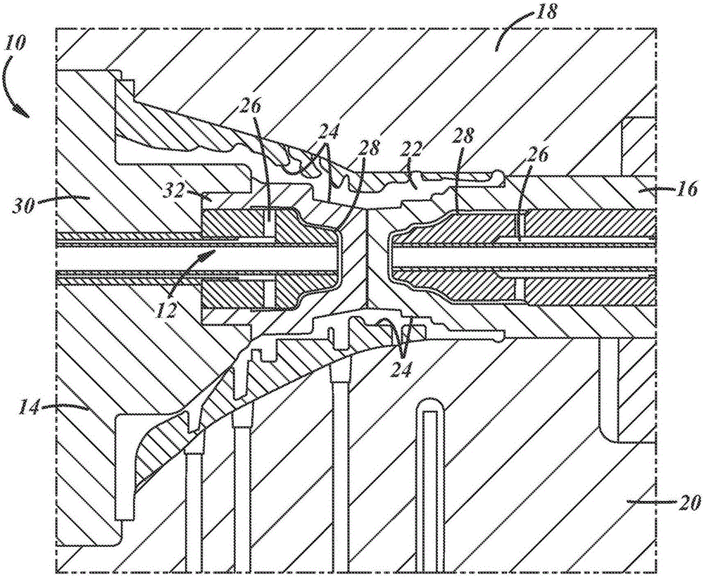
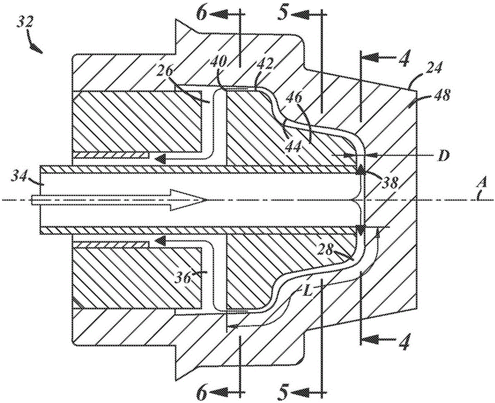
[0027] Tooling for shaping heated materials and cooling them to form finished articles is described below. The tool includes a cooling system having one or more cooling channels formed in the tool. When the heated material is in contact with the forming surface of the tool, the coolant flows along the cooling channels and extracts heat from the heated material to help transform the material into a desired shape and / or state. The cooling channels can be configured as described below to greatly increase the rate of heat extraction from the heating material by bringing the cooling liquid to its boiling point and using the latent heat of evaporation of the cooling liquid to cool the heating material.

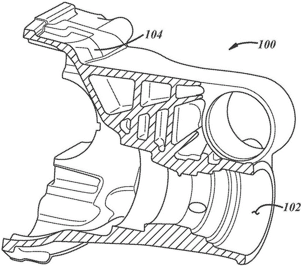
[0028] see now figure 1 , shows an exemplary forming tool 10 in the form of a casting mold. The casting mold 10 includes a cooling system 12 and is configured to shape the molten material into a cast or molded article, such as, figure 2 Housing 100 is shown. In one particular e...


PUM


Abstract

A shaping tool (10, 110) includes a cooling system (12) having one or more cooling passages (26, 126) configured for enhanced cooling. The cooling passages provide latent heat cooling of a heated material that is in contact with a shaping surface (24, 124) of the tool. Cooling fluid flows along the cooling passages in a two-phase flow regime in which a portion of the cooling fluid is liquid and a portion of the cooling fluid is vapor. A two-phase portion (28, 128) of the cooling passage can be shaped to follow a three-dimensional contour of the shaping surface. Opposing walls of the cooling passage can be provided by passage surfaces (42, 44, 142, 144) of separately formed pieces of the tool. The latent heat cooling provided by suitably configured cooling channels extracts more heat from the material being shaped in the tool than traditional cooling systems.

Description

[0001] References to related applications [0002] This application claims priority to US Provisional Application Serial No. 61 / 949,480, filed March 7, 2014, the entire contents of which are hereby incorporated by reference. technical field [0003] The present invention relates to cooling systems for use in tools for forming material and methods of making and using such cooling systems and tools. Background technique [0004] Heat-related defects are a continuing problem in the forming and particularly casting of heated materials. Increased complexity of cast parts, demands for higher production rates, and demands for lower scrap rates all tend to increase the thermal load on the mold cooling system. A typical cooling system usually consists of many channels drilled or cut into the tool through which liquid coolant is to flow. This is a single phase system where heat is transferred from the mold surface (which is in contact with the material to be formed), through the mat...

Claims


Application Information

Patent Timeline
Patent Type & Authority Applications(China)
IPC IPC(8): B29C45/73B29C45/26
CPCB22D17/2218B21D22/022B21D37/16B22C9/065B29C45/7337B29C51/428B29C2045/7362
Inventor 亚历山大·雷克赫拉克利福德·杰森·霍希欧尔
Owner 格鲁帕铸造有限责任公司
Why Eureka
Try Eureka