Turbine for sand mill

A sand mill and turbine technology, applied in the field of sand mills, can solve the problems of sufficient separation of materials that cannot be ground well, materials with large particles and grinding beads, limited centrifugal force, etc., to achieve improved grinding efficiency, stable bead flow, and centrifugal force. strong effect

Inactive Publication Date: 2016-12-07
CHANGZHOU LONGXIN MACHINERY
View PDF9 Cites 2 Cited by
  • Summary
  • Abstract
  • Description
  • Claims
  • Application Information

AI Technical Summary

Problems solved by technology

The grinding part adopts a centrifugal turbine. The centrifugal force generated by the existing structure of the centrifugal turbine is limited, and it cannot fully separate the ground material from the material with large particles and the grinding beads.

Method used


Image

  • Turbine for sand mill
  • Turbine for sand mill
  • Turbine for sand mill

Examples


Embodiment Construction

[0022] The present invention will be described in detail in conjunction with accompanying drawing now. This figure is a simplified schematic diagram only illustrating the basic structure of the present invention in a schematic manner, so it only shows the components relevant to the present invention.

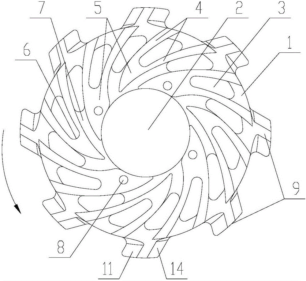
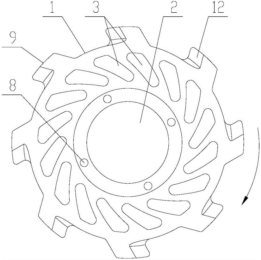
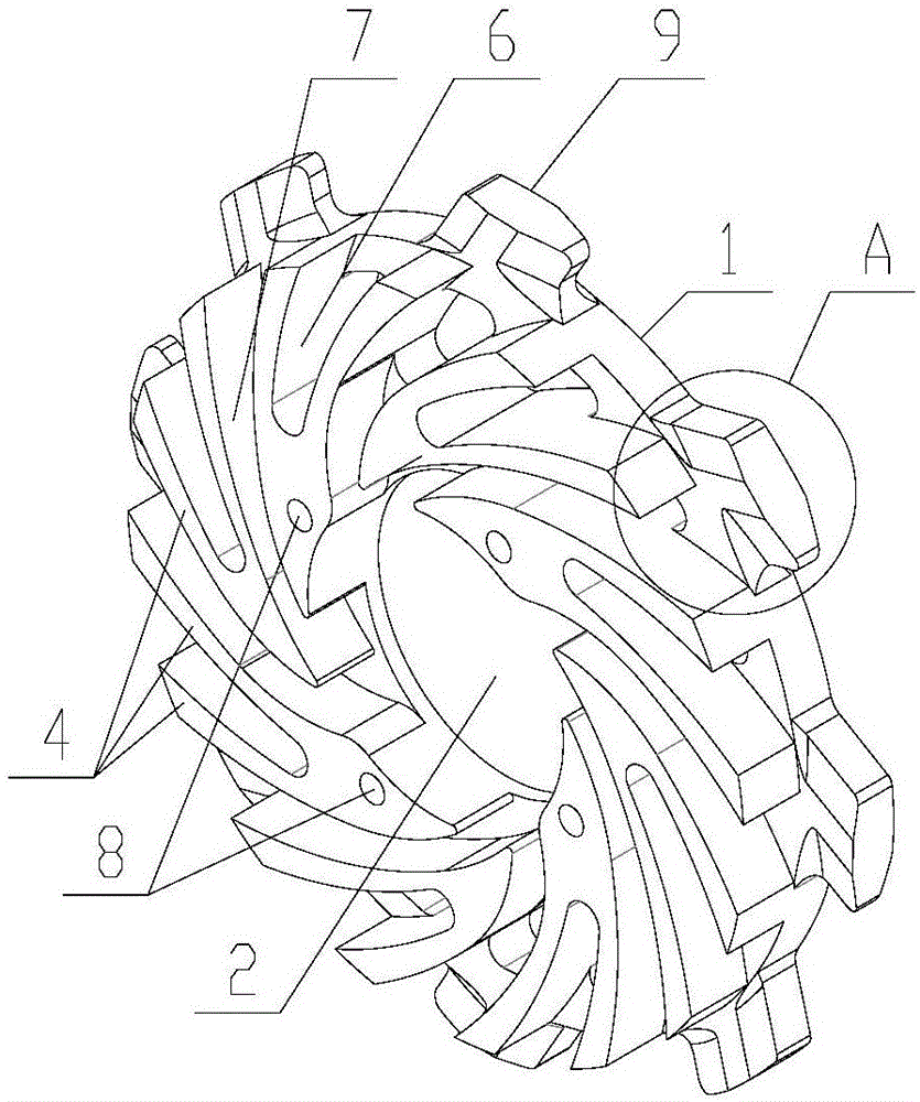
[0023] Such as Figure 1-4 As shown, a kind of turbine for sand mill of the present invention comprises base plate 1, and the center of base plate 1 is provided with shaft hole 2, and sixteen inclined guide holes 3 are uniformly distributed along the circumference of base plate 1, and described guide hole 3 The direction of inclination is opposite to the direction of rotation of the turbine, the width of the guide hole 3 gradually increases from one end close to the shaft hole 2 to the other end, and each side of the guide hole 3 adopts a streamline design; two adjacent guide holes 3 The bottom plate 1 between is provided with a axially protruding centrifugal blade 4, and the c...


PUM


Abstract

The invention provides a turbine for a sand mill. The turbine comprises a bottom plate, wherein a plurality of oblique guide holes are uniformly formed in the bottom plate around the circumference; the oblique direction of each guide hole is opposite to the rotary direction of the turbine; a centrifugal blade is arranged on one side face of the bottom plate between every two adjacent guide holes, and the oblique direction of each centrifugal blade is the same as that of the guide hole; a plurality of oblique screws are uniformly distributed on the outer circumference of the bottom plate, the oblique direction of each screw in the cross section of the bottom plate is opposite to the rotary direction of the turbine; and a first section and a second section extending in the radial direction are arranged on two sides of the rear of each screw and are in mirror symmetry to enable the thickness of the screw to be gradually decreased from front to back in the rotary direction. According to the invention, intense centrifugal design that the screws are arranged on the outer circumference of the bottom plate is adopted to thoroughly separate small grinding media from a material, so that grinding is more sufficient; and in addition, the screws are additionally arranged on the circumference of the turbine to improve the grinding efficiency of the turbine sand mill, and the screws adopt bionic shapes to generate stronger bead flows and further reduce energy consumption.

Description

technical field [0001] The invention relates to the technical field of sand mills, in particular to a turbine for sand mills. Background technique [0002] The sand mill is mainly used for wet grinding of chemical liquid products, including a grinding container, a main shaft and grinding parts. There is a grinding chamber in the grinding container, and the grinding parts are located in the grinding chamber. The main shaft drives the grinding parts, and the materials entering the grinding chamber are ground Parts and grinding beads for grinding. The grinding part adopts a centrifugal turbine. The centrifugal force generated by the existing structure of the centrifugal turbine is limited, and it cannot fully separate the ground material from the material with large particles and the grinding beads. Contents of the invention [0003] The technical problem to be solved by the invention is: in order to overcome the limitation of the centrifugal force generated by the turbine i...

Claims


Application Information

Patent Timeline
Patent Type & Authority Applications(China)
IPC IPC(8): B02C15/00
CPCB02C15/003
Inventor 陆小虎莫铭伟
Owner CHANGZHOU LONGXIN MACHINERY
Why Eureka
Try Eureka