
Ball-stirring mill for convex pin turbine

A technology of stirring mill and turbine, applied in grain processing and other directions, can solve the problems of high application, high cost and low cost, and achieve the effect of large stirring effect, good crushing effect and strong shearing force.

Active Publication Date: 2013-06-26
深圳市叁星飞荣机械有限公司
View PDF6 Cites 2 Cited by
  • Summary
  • Abstract
  • Description
  • Claims
  • Application Information

AI Technical Summary

Problems solved by technology

The disc-type medium agitated mill is simple and low in cost, but its grinding efficiency is low, and it is difficult to prepare grinding products with a particle size below 5 microns
The pin-pin media stirring mill has a better stirring function and a more uniform particle size distribution, but the grinding effect is still not ideal. Repeated grinding is required to make the particle size of the product below 5 microns. high energy
The grinding efficiency of the turbine-type medium agitated mill is similar to that of the pin-pin type. It drives the fluid to circulate in a circular flow and radially. The shear force generated by the speed between the grinding beads formed in the center is not as strong as that of the pin type, and the grinding efficiency of the two is similar. The turbine type is more difficult to manufacture and more expensive.

Method used


Image

  • Ball-stirring mill for convex pin turbine
  • Ball-stirring mill for convex pin turbine
  • Ball-stirring mill for convex pin turbine

Examples


Embodiment Construction

[0015] In order to better understand the present invention, the present invention will be further described below in conjunction with the accompanying drawings.

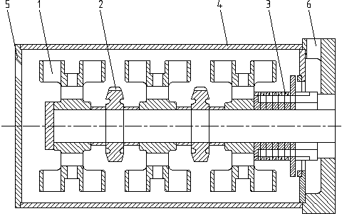
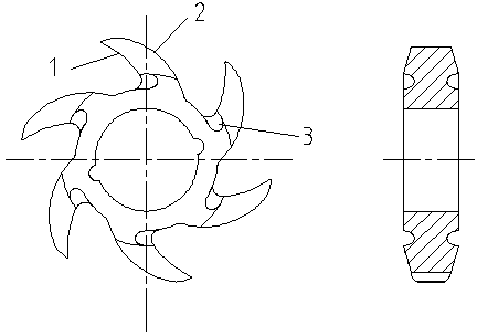
[0016] Such as figure 1 Therefore, the convex pin turbine medium agitated mill of the present invention includes: the convex pin turbine 1, the claw wheel 2, the bead separator combination 3, the grinding chamber cylinder 4, the feeding gap cover 5, and the discharge chamber 6.

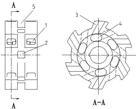
[0017] Such as figure 2 As shown, the circumferences of the two ends of the lug-pin turbine are evenly divided into several lug pins, and the center position of the lug pin is cut out and the oblique hole is connected with the inner circle of the turbine to form a vortex groove, which is called the lug-pin turbine flow groove, and several holes are opened in the radial direction of the turbine. A through hole, in the center of the middle groove between the two circles of convex pins, several inclined holes are opened to communicate with th...


PUM


Abstract

The invention provides a ball-stirring mill for a convex pin turbine. The ball-stirring mill comprises one or more convex pin turbines, zero or more jaw wheels, a material-ball separating assembly, a milling cavity cylinder body, a charging cylinder cover and a discharging room, wherein a plurality of convex pins are arranged on the turbine(s), and the middle parts of the convex pins are hollowed to form vortex grooves; each turbine is provided with a plurality of through holes along the radial direction, and the through holes are communicated with the plurality of middle vortex grooves; and when the turbines run, a sizing agent and a milling media (i.e. milling balls) are driven to circularly move along the peripheral direction and the radial direction, and a high shearing force is generated by the stirring function of the pins. When the jaw wheels rotate, a powerful centripetal driving force is generated. The materials thrown out of the turbine and the milling balls are driven to enter inner holes of the turbines, so that the circular flow can be enhanced. According to the ball-stirring mill, a circular driving force and a stirring force of liquid are enhanced, so that the milling efficiency can be greatly improved, and the granularity of products milled for once can be obviously reduced; and therefore, the ball-stirring mill can be wildly applicable to the field of extra-fine grinding and extra-fine dispersing of materials, and in particular, the ball-stirring mill has preferable effects on the extra-fine grinding and dispersing of prepared nanometer-level products or high-viscosity products.

Description

technical field [0001] The invention belongs to the field of vertical or horizontal medium stirring mills, in particular to a convex pin turbine medium stirring mill. Background technique [0002] Ordinary vertical or horizontal media agitated mills can be roughly divided into three categories according to their agitating rotor structure: disc type, pin pin type, and turbine type. Widely used in the field of wet grinding in coatings, inks, dyes, electronic materials, biology, pharmaceuticals, cosmetics and other industries. The disk-type medium agitated mill is simple and low in cost, but its grinding efficiency is low, and it is difficult to prepare grinding products with a particle size below 5 microns. The pin-pin media stirring mill has a better stirring function and a more uniform particle size distribution, but the grinding effect is still not ideal. Repeated grinding is required to make the particle size of the product below 5 microns. high energy is required. The ...

Claims


Application Information

Patent Timeline
Patent Type & Authority Applications(China)
IPC IPC(8): B02C17/16B02C17/18
Inventor 谢小飞
Owner 深圳市叁星飞荣机械有限公司
Learn More