Cleaning device for continuous blowdown expander

A technology for cleaning devices and expanders, which is applied in the direction of steam separation devices, cleaning hollow objects, chemical instruments and methods, etc., can solve the problems of labor and time consumption, limited effect of rotating centrifugation, and difficult cleaning, etc., to improve adaptability and Targeted, significant cleaning effect, increased cleaning effect

Inactive Publication Date: 2016-12-07
CHENGDU 90 DEGREE IND PROD DESIGN CO LTD
View PDF8 Cites 0 Cited by
  • Summary
  • Abstract
  • Description
  • Claims
  • Application Information

AI Technical Summary

Problems solved by technology

[0003] The existing continuous blowdown expander has the following defects in use: when the cleaning water rotates through the water inlet pipe and enters the cavity, the spiral rotation path causes the cleaning to be incomplete, and the dirt attached to the inner wall of the cylinder cannot be removed. Thoroughly eliminate, especially for some dirt particles with strong adhesion, the effect of rotating and centrifuging the cleaning water alone is often limited and cannot achieve the effect of thorough removal. At the same time, in order to ensure the cleaning effect, it is often necessary to inject A large amount of cleaning water leads to a large demand for cleaning water, resulting in a certain waste of water resources, which is not conducive to the energy saving and emission reduction of enterprises
In addition, the existing cleaning devices for continuous blowdown expanders all set the cleaning water device to be inclined downward, or to keep parallel to the radial direction of the cavity. It is not easy to be cleaned, and it takes a long time to clean the inner wall of the cavity, which further increases the consumption of cleaning water and is labor-intensive and time-consuming

Method used


Image

  • Cleaning device for continuous blowdown expander
  • Cleaning device for continuous blowdown expander
  • Cleaning device for continuous blowdown expander

Examples


Embodiment Construction

[0031] Below in conjunction with embodiment, the present invention is described in detail.

[0032] In order to make the object, technical solution and advantages of the present invention more clear, the present invention will be further described in detail below in conjunction with the examples. It should be understood that the specific embodiments described here are only used to explain the present invention, not to limit the present invention.

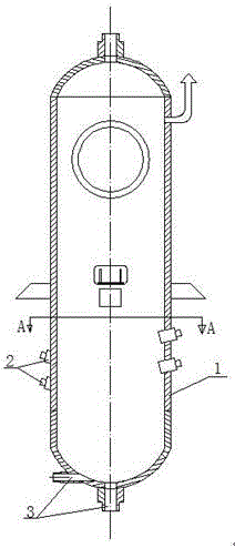
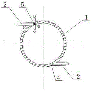
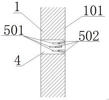
[0033] Such as figure 1 with figure 2 As shown, a cleaning device for a continuous blowdown expander includes a cavity body 1, a cleaning water inlet pipe 2 is provided at the lower part of the cavity body 1, and the cleaning water inlet pipe 2 is distributed on the cavity body 1, and a cleaning water inlet pipe 2 is arranged below the cleaning water inlet pipe 2. There is a sewage outlet 3, and the cleaning water inlet pipe 2 adopts a tangential oblique intubation structure. The connection between the cleaning water inlet pipe 2 a...


PUM


Abstract

The invention discloses a cleaning device for a continuous blowdown expander, comprising a cavity, a cleaning water inlet pipe is arranged at the lower part of the cavity, the cleaning water inlet pipe adopts a tangential oblique intubation structure, and the cleaning water inlet pipe is connected with the cavity. A cavity opening is formed, and along the axial direction of the cavity, there are a plurality of cleaning water inlet pipes evenly distributed, and the cleaning water inlet pipes on both sides of the cavity are staggered. The device is used to divide the cleaning water in the cleaning inlet pipe along the direction of the wall surface of the cavity. By staggering the cleaning inlet pipes and cooperating with the shunt adjustment device, the impulse loss of the cleaning water is small, the cleaning effect is remarkable, the duration is short, the water resources are saved, the defects of the existing cleaning device are solved, and the cleaning device can adapt to The cleaning of various dirt particles improves the adaptability and pertinence of the cleaning device, thereby diversifying the functions of the cleaning device.

Description

technical field [0001] The invention relates to the field of boiler blowdown equipment, in particular to a cleaning device for a continuous blowdown expander. Background technique [0002] The continuous blowdown expander is also called the continuous blowdown expander. Its function is to separate the steam and sewage at the boiler blowdown expansion evaporation place. The separated steam can be recycled to the thermal system, and the unevaporated blowdown water can be sent to the blowdown Cooler to heat softened water etc. The continuous blowdown expander uses the principle of flash evaporation to obtain secondary steam. The boiler blowdown water with certain parameters is suddenly input from the pipeline into the expander whose volume is several times larger than the pipeline. The pressure decreases and the volume increases, thereby flashing The steam evaporates. The continuous sewage discharger relies on ion separation, gravity separation and molecular friction separati...

Claims


Application Information

Patent Timeline
Patent Type & Authority Applications(China)
IPC IPC(8): B08B9/093F22B37/26
CPCB08B9/093F22B37/26
Inventor 卢晔
Owner CHENGDU 90 DEGREE IND PROD DESIGN CO LTD
Why Eureka
Try Eureka