Steel coil longitudinal shearing equipment with synchronous edge wire collecting function

A side wire and slitting technology, which is applied in metal processing equipment, other manufacturing equipment/tools, shearing devices, etc., can solve problems such as difficult collection, easy scratching of side wire, and potential safety hazards, and achieve convenient and quick collection and elimination Potential safety hazards and convenient collection

Inactive Publication Date: 2016-12-07
江苏高尔德汽车钢管有限公司
View PDF7 Cites 1 Cited by
  • Summary
  • Abstract
  • Description
  • Claims
  • Application Information

AI Technical Summary

Problems solved by technology

[0004] However, when the slitting device is in operation, if there are too many side wires in the deep pit or the trimmed side wires do not fall in time, it is easy for the side wires to run out of the range of the deep pit, and the running out side wires are very easy to scratch The steel belt may cause injury to the personal safety of the operator
At the same time, after the slitting operation is completed, personnel need to enter the deep pit to clean the side wires. The side wires are easy to scratch the workers and are not easy to collect. The deep pit is difficult to clean, and the cleaning process is cumbersome and time-consuming.
In addition, there are often people or goods passing on both sides of the steel coil slitting equipment, and the risk of people or goods falling into the deep pit is very high, so the existence of the deep pit itself is a big safety hazard

Method used


Image

  • Steel coil longitudinal shearing equipment with synchronous edge wire collecting function
  • Steel coil longitudinal shearing equipment with synchronous edge wire collecting function
  • Steel coil longitudinal shearing equipment with synchronous edge wire collecting function

Examples


Embodiment Construction

[0021] The present invention will be further described in detail below in conjunction with the drawings.

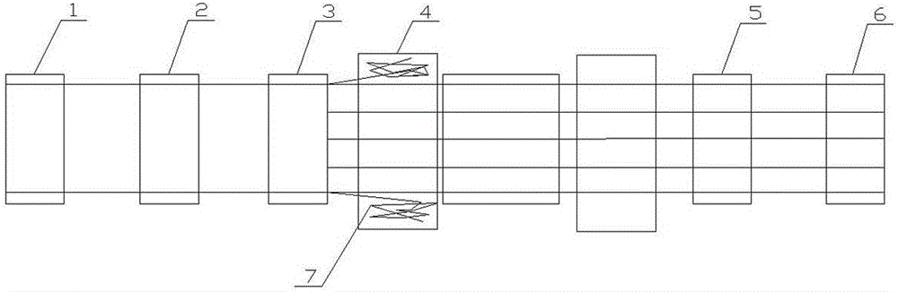
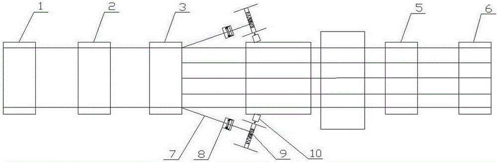
[0022] Such as figure 2 , image 3 , Figure 4 with Figure 5 As shown, the steel coil slitting equipment with synchronous edge wire collection function of the present invention includes a feeding device 1, a leveling device 2, a slitting device 3, a separating device 5, and a receiving device 6 arranged in a straight line. Both sides of the extension line of the rear end of the slitting device 3 are provided with a side wire winding shaft 9, and one end of the side wire winding shaft 9 is connected with a motor 10.

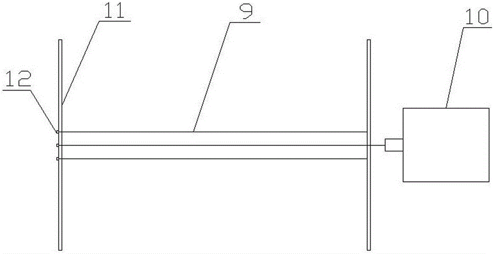
[0023] Both ends of the edge wire winding shaft 9 are provided with baffles 11. The baffle 11 at one end of the side wire winding shaft 9 away from the motor 10 is detachably connected to the side wire winding shaft 9. In this embodiment, a fastening nut 12 is used to connect the baffle 11 and the side wire winding shaft 9 together.

[0024] The angle between t...


PUM


Abstract

The invention relates to steel coil longitudinal shearing equipment, in particular to steel coil longitudinal shearing equipment with a synchronous edge wire collecting function. The steel coil longitudinal shearing equipment comprises a feeding device, a straightening device, a longitudinal shearing device, a separation device and a collecting device which are sequentially distributed in a linear mode. The steel coil longitudinal shearing equipment is characterized in that edge wire rolling shafts are arranged on the two sides of the extending line at the rear end of the longitudinal shearing device, and motors are connected to one ends of the edge wire rolling shafts. According to the steel coil longitudinal shearing equipment, edge wires can be collected conveniently and quickly while steel coil longitudinal shearing is conducted, the phenomenon of wire moving in the collecting process is avoided, operators can not be injured, the edge wires do not need to be cleaned specially after longitudinal shearing, and potential safety hazards are avoided.

Description

Technical field [0001] The invention relates to a steel coil slitting equipment, in particular to a steel coil slitting equipment with a synchronous edge wire collection function, which can conveniently and quickly collect the cut edge wires while the steel coil is slit. Background technique [0002] Coil slitting equipment, as the name implies, is an equipment for longitudinally cutting the steel plate wound in the coil. In order to meet the requirements for the width of the steel coil after slitting, a certain width range must be reserved at both ends of the steel coil before slitting, so as to ensure that the edges of the steel coil after slitting do not have gaps and are cut neatly. The part reserved at both ends of the steel coil becomes the edge wire after cutting. [0003] At present, the known steel coil slitting equipment is composed of a feeding device 1, a leveling device 2, a slitting device 3, a separating device 5 and a receiving device 6 in series (such as figure 1 ...

Claims


Application Information

Patent Timeline
Patent Type & Authority Applications(China)
IPC IPC(8): B23P23/04B23D33/00B21C47/02
CPCB23P23/04B21C47/02B23D33/00
Inventor 丁子怡
Owner 江苏高尔德汽车钢管有限公司
Why Eureka
Try Eureka