Clamping structure for grinding bar of medical grinding machine

A technology of clamping structure and grinding machine, which is applied in the field of medical equipment, can solve problems such as clamping, slipping, and inability to pull out, and achieve the effect of improving grinding accuracy

Inactive Publication Date: 2016-12-07
武汉多可特医疗器械有限公司
View PDF6 Cites 2 Cited by
  • Summary
  • Abstract
  • Description
  • Claims
  • Application Information

AI Technical Summary

Problems solved by technology

Therefore, the thickness of the clamping part, the increased wear of the inner hole of the three-lobe chuck and the blockage of the cuttings all directly affect the clamping effect, so that there are slipping, clamping not tight, and pulling out phenomena in actual work.

Method used


Image

  • Clamping structure for grinding bar of medical grinding machine
  • Clamping structure for grinding bar of medical grinding machine
  • Clamping structure for grinding bar of medical grinding machine

Examples


Embodiment Construction

[0024] The present invention will be further described below in conjunction with the accompanying drawings and embodiments.

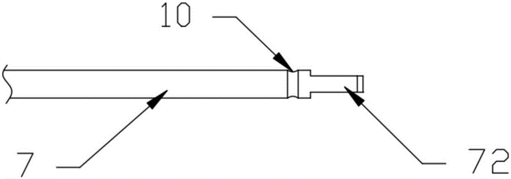
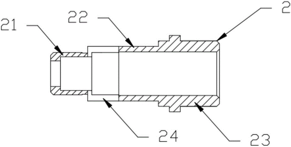
[0025] Such as Figure 1 to Figure 4 As shown, the present invention provides a medical grinder rod clamping structure, the grinder body 1, the first sleeve 2, the second sleeve 3, the locking mechanism 4, the steel ball 5, the transmission shaft 6 and the grinder 7. The transmission shaft 6 is coaxially connected with the grinding rod 7, and the grinding rod sleeve 9 connected with the grinding rod 7 is provided on the outside of the grinding rod 7; Support sleeve one 21, support sleeve two 22 and support sleeve three 23, the end inner wall of the support sleeve three 23 is connected with the outer wall of the transmission shaft 6 through the first bearing 13, the outer wall of the support sleeve one 21 is threaded with the inner wall of the grinding rod sleeve 9 Connected, the grinding rod 7 passes through the opening of the support sleeve 1 21, and ...


PUM


Abstract

The invention provides a clamping structure for a grinding bar of a medical grinding machine. The clamping structure comprises a first sleeve tube (2), a second sleeve tube (3), a push block (42), a taper sleeve (41) and steel balls (5). The second sleeve tube (3) is provided with slotted holes (8) with the diameter of lower openings being smaller than that of upper openings, and the steel balls (5) are arranged in the slotted holes (8). The taper sleeve is connected to the second sleeve tube in a sleeving mode, is in sliding connection with the second sleeve tube and is used for limiting the steel balls (5). The push block is used for pushing the taper sleeve to move. By the adoption of the clamping structure, axial vertical rigid force can be applied to the grinding bar through the steel balls, the problem of steel ball skewing caused by vibration in the working process of the grinding machine and pressure to the steel balls by the grinding bar cannot happen, and the phenomena that the grinding bar slips, cannot be clamped tightly and cannot be pulled out due to abrasion increase of three-petal chuck inner holes and blockage by cutting objects are avoided.

Description

technical field [0001] The invention relates to the field of medical instruments, in particular to a clamping structure for a grinding rod of a medical grinder. Background technique [0002] There are generally two basic ways to clamp the grinding rod of traditional medical grinding machines, one is the three-petal chuck, and the other is steel ball clamping: [0003] The three-lobe chuck is the most commonly used clamping method. The grinding head adopting this method generally includes an elastic three-lobe chuck, a rear pull rod threaded with it, a compression spring set on the rear pull rod, and a set of three Other than the long body and so on. When working, the transmission of dynamic parameters such as torque and rotational speed is completed by the friction between the inner hole surface of the elastic three-lobe chuck and the clamping part of the grinding rod. Therefore, the thickness of the clamping part, the increased wear of the inner hole of the three-lobed ch...

Claims


Application Information

Patent Timeline
Patent Type & Authority Applications(China)
IPC IPC(8): B24B45/00
CPCB24B45/00
Inventor 管新贤陈登奇付长魁刘坤峰刘伟陈光明
Owner 武汉多可特医疗器械有限公司
Why Eureka
Try Eureka