
Parallel extension and retraction type double-arm robot
A telescopic and robotic technology, applied in the field of robotics, can solve problems such as the inability to effectively arrange two robots at the same time, the inability to complete coordinated actions, and line obstacles
- Summary
- Abstract
- Description
- Claims
- Application Information
AI Technical Summary
Problems solved by technology
Method used
Image

Examples
Embodiment Construction
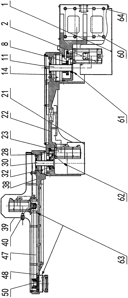
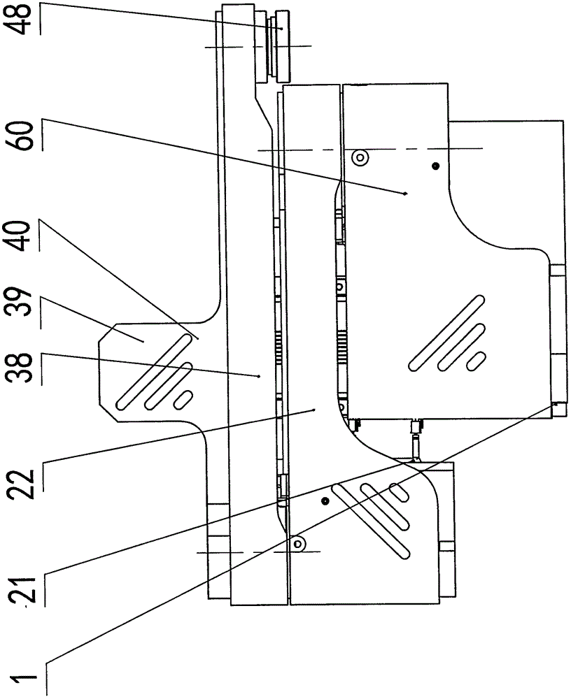
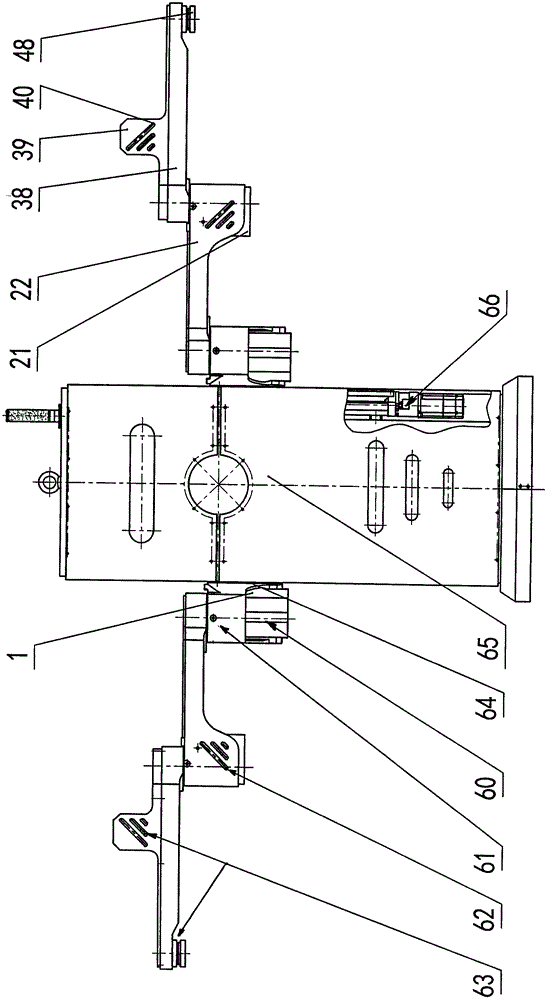
[0013] Refer to attached image 3 , the parallel telescopic dual-arm robot of the present invention comprises a cabinet (i.e. a fuselage) 65 and a lifting arm 60, and the lifting arm 60 is two pieces and is mounted on the left and right sides of the cabinet 65 respectively, and a straight line is installed in the cabinet 65. Module 66 (also left and right two groups, all including linear guide rail, screw mandrel, lifting motor etc., are used to control the lifting of lifting arm 60) and link to each other with lifting arm 60 by respective slide block 64, described lifting arm The other end of 60 is successively connected with the first rotating arm 22, the second rotating arm 38, and the end rotating flange 48 (both are respectively left and right symmetrical groups). This cabinet (being fuselage) 65 contains electrical control elements such as servo driver, motion controller, microcomputer controller.
[0014] refer to figure 1 , figure 2 , the lifting arm 60 is connecte...
PUM
 Abstract
Description
Claims
Application Information