Automobile front device based on pedestrian protection
A front-mounted device, automobile technology, applied in pedestrian/occupant safety arrangement, vehicle components, transportation and packaging, etc., can solve problems such as loss, pedestrian injury, etc., and achieve the effect of shortening collision time, reducing injury, and increasing distance
- Summary
- Abstract
- Description
- Claims
- Application Information
AI Technical Summary
Problems solved by technology
Method used
Image
Examples
specific Embodiment approach 1
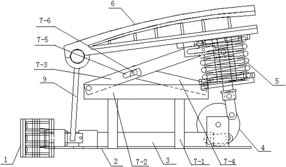
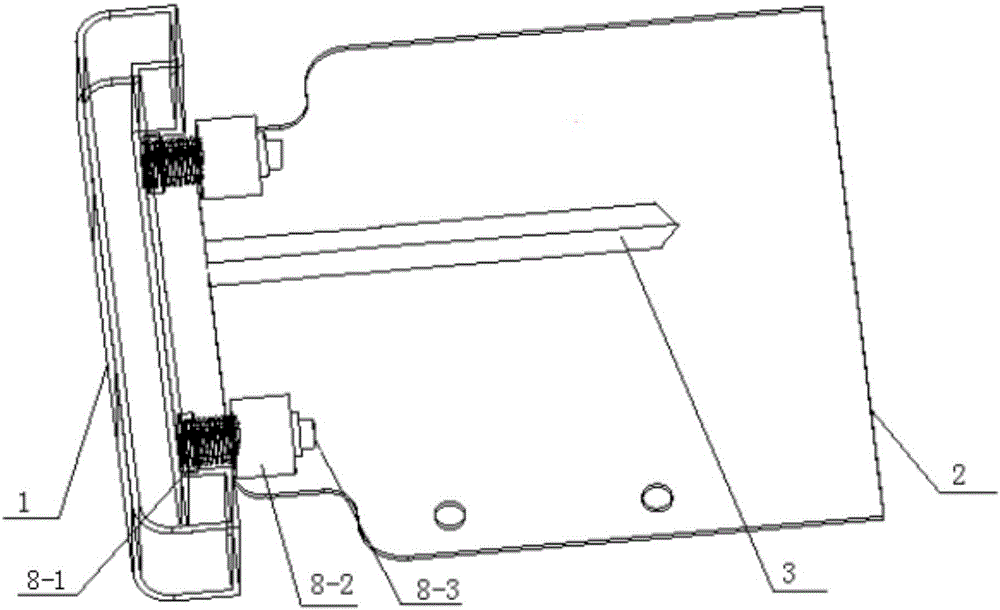
[0018] Specific implementation mode one: combine figure 1 , figure 2 , image 3 and Figure 4 Describe this embodiment. This embodiment includes a front elastic force adjustment assembly, a base plate 2, a trigger lever 3, a cam mechanism 4 and a lifting mechanism 5. The front bumper 1 of the automobile is fixedly installed on the base plate 2 through the front elastic force adjustment assembly. Above, the trigger lever 3 is located on the base plate 2 and its front end is fixedly connected with the front bumper 1, the rear end of the trigger lever 3 is hinged on the cam mechanism 4, and a lifting mechanism 5 is arranged above the cam mechanism 4, so that The cam mechanism 4 is connected with the engine cover 6 of the automobile through the lifting mechanism 5, and the engine cover 6 of the automobile makes an inclination towards the front bumper 1 under the adjustment of the lifting mechanism 5.
[0019] The present invention makes the front bumper 1 of automobile become ...
specific Embodiment approach 2
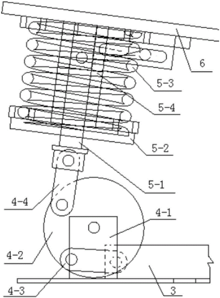
[0020] Embodiment 2: This embodiment is a further limitation of Embodiment 1. In this embodiment, the cam mechanism 4 includes a base 4-1, a cam body 4-2, a first connecting rod 4-3 and a second connecting rod. 4-4, the base 4-1 is detachably connected to the bottom plate 2, the cam body 4-2 is hinged on the base 4-1, and one side of the cam body 4-2 is sequentially provided with a first connecting rod 4 -3 and the second connecting rod 4-4, one end of the first connecting rod 4-3 is hinged on the cam body 4-2, and the other end of the first connecting rod 4-3 is hinged with the rear end of the trigger lever 3 , one end of the second connecting rod 4-4 is hinged on the cam body 4-2, and the other end of the second connecting rod 4-4 is hinged on the lifting mechanism 5.
[0021] In this embodiment, when the trigger lever 3 moves backward, that is, toward the direction of the cam body 4-2, the trigger lever 3 drives the first connecting rod 4-3 to move, and the first connecting...
specific Embodiment approach 3
[0022] Embodiment 3: This embodiment is a further limitation of Embodiment 2. In this embodiment, the lifting mechanism 5 includes a connecting pin 5-1, a lower support member 5-2, a first spring 5-3 and a safety lock pin 5 -4, the lower support 5-2 is set away from the front bumper 1 and is located below the engine cover 6, the bottom of the lower support 5-2 is connected to the second connecting rod 4- through the connecting pin 5-1 The other end of 4 is hinged, the first spring 5-3 is arranged between the lower support 5-2 and the engine cover 6, the safety lock pin 5-4 is passed through the first spring 5-3, The safety lock pin 5-4 includes an upper connecting piece 5-4-1, a lower connecting piece 5-4-2, an upper component pin 5-4-3, a lower component pin 5-4-4, and an inner cylinder 5-4 -5 and lock bar 5-4-6, upper connecting piece 5-4-1, upper component pin 5-4-3, lower component pin 5-4-4 and lower connecting piece 5-4-2 from top to bottom Set in sequence, the upper en...
PUM
 Abstract
Description
Claims
Application Information
 - R&D
- Intellectual Property
- Life Sciences
- Materials
- Tech Scout
- Unparalleled Data Quality
- Higher Quality Content
- 60% Fewer Hallucinations
Browse by: Latest US Patents, China's latest patents, Technical Efficacy Thesaurus, Application Domain, Technology Topic, Popular Technical Reports.
© 2025 PatSnap. All rights reserved.Legal|Privacy policy|Modern Slavery Act Transparency Statement|Sitemap|About US| Contact US: help@patsnap.com


