A dyeing machine head squeeze water cloth out device

A dyeing machine and machine head technology, which is applied in the field of printing and dyeing, can solve problems such as excessive water entrainment, and achieve the effects of improving the effect, preventing pollution, and reducing the intensity of labor operations

Active Publication Date: 2018-07-31
浙江亚东机械有限公司
View PDF11 Cites 0 Cited by
  • Summary
  • Abstract
  • Description
  • Claims
  • Application Information

AI Technical Summary

Problems solved by technology

[0003] The purpose of the present invention is to solve the above-mentioned problems in the existing technology, and propose a device for squeezing water out of the head of the dyeing machine to solve the problems of entraining too much water in the cloth separation and dyeing machine

Method used


Image

  • A dyeing machine head squeeze water cloth out device
  • A dyeing machine head squeeze water cloth out device
  • A dyeing machine head squeeze water cloth out device

Examples


Embodiment Construction

[0031] The following are specific embodiments of the present invention and in conjunction with the accompanying drawings, the technical solutions of the present invention are further described, but the present invention is not limited to these embodiments.

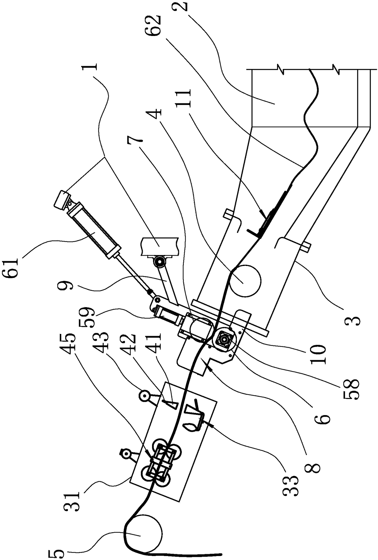
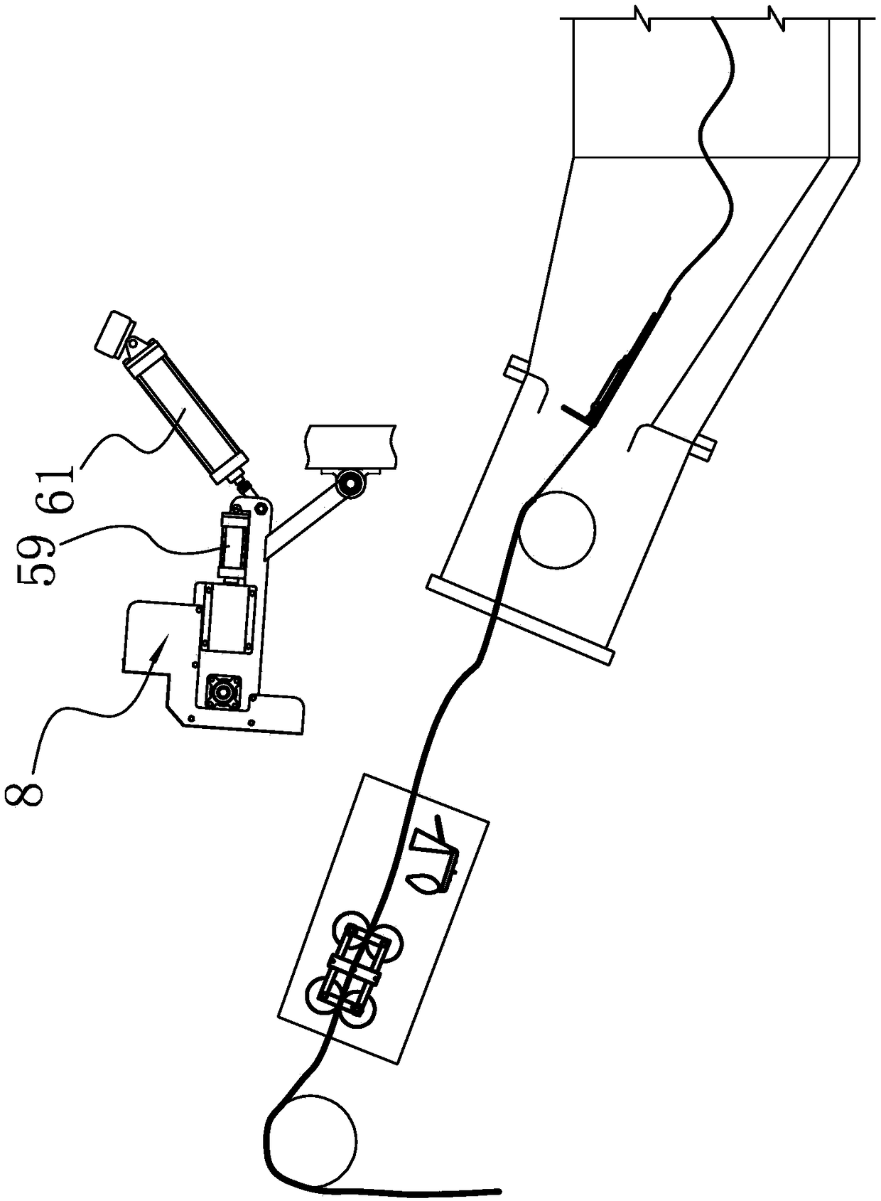
[0032] Such as figure 1 and figure 2 As shown in the figure, a dyeing machine head squeezes water out of the cloth device. The dyeing machine includes a frame 1, a dyeing vat 2 and a cloth outlet guide cylinder 3. The bottom end of the cloth outlet guide cylinder 3 communicates with the dye vat 2, and the top is the cloth outlet of the machine head. end, the cloth outlet guide cylinder 3 is provided with a cloth guide wheel 4 for pulling the cloth 62 out of the dye vat 2, and the frame 1 is provided with a cloth outlet wheel for collecting the cloth coming out of the top port of the cloth outlet guide cylinder 3 5. Both the dyeing vat 2 and the cloth outlet guide cylinder 3 are fixed on the frame 1. It is characterized i...


PUM


Abstract

The invention provides a head squeezing and cloth discharging device for a dyeing machine, belongs to the technical field of printing and dyeing, and solves the technical problems that after cloth is dyed by the conventional dyeing machine, the cloth adsorbs a dye liquor, the dye liquor is wasted, and the cloth collection and transportation are inconvenient. According to the head squeezing and cloth discharging device for the dyeing machine, the dyeing machine comprises a rack, a dyeing cylinder and a discharged cloth guiding cylinder, and is characterized in that a roller assembly is arranged outside the top end opening of the discharged cloth guiding cylinder; the roller assembly comprises a driving roller and a compressing roller; the driving roller is connected with a driving mechanism capable of enabling the driving roller to rotate; the compressing roller is enabled to be propped against or away from the driving roller through a compressing mechanism; a hinge rod is arranged at the top of a support and is hinged to the rack; a lifting mechanism is connected with the top of the rack; the roller assembly is enabled to be near or away from the top end opening of the discharged cloth guiding cylinder through the lifting mechanism; a water guide groove is fixed on the rack. The head squeezing and cloth discharging device for the dyeing machine has the advantage that the dewatering effect of the dyed cloth is good.

Description

technical field [0001] The invention belongs to the technical field of printing and dyeing, and relates to a dyeing machine, in particular to a cloth squeezing device for a head of the dyeing machine. Background technique [0002] After the dyeing machine finishes dyeing the cloth and other fabrics, the cloth is separated from the dyeing machine and dropped into the cloth storage car. When the cloth is discharged, the water in the dyeing machine is basically washed liquid. This water can be used in the next operation of dyeing the fabric, but When the fabric comes out, part of the water will be taken out of the dyeing machine through the fabric, and a large amount of water will flow into the sewage ditch or the cloth storage vehicle when the fabric is discharged, resulting in an increase in sewage consumption, resulting in a waste of water resources or an increase in the weight of the storage vehicle. Large, increasing the labor intensity of the operator, and the fabrics in ...

Claims


Application Information

Patent Timeline
Patent Type & Authority Patents(China)
IPC IPC(8): D06B15/02D06B23/04D06B23/20D06B23/00D06B15/00D06C15/02
CPCD06B15/00D06B15/02D06B23/00D06B23/04D06B23/20D06C15/02
Inventor 胡志峰王立锋韩敏祺
Owner 浙江亚东机械有限公司
Why Eureka
Try Eureka