Locating and mounting method for H-shaped steel girder butting joints

An installation method and node positioning technology, which are applied in the construction, building structure, processing of building materials, etc., can solve the problems such as the time required cannot be accurately predicted, the continuity of the operation process is restricted, and the overlapping time is long. Simple, low-cost, easy-to-make effects

Active Publication Date: 2016-12-07
CHINA FIRST METALLURGICAL GROUP
View PDF7 Cites 29 Cited by
  • Summary
  • Abstract
  • Description
  • Claims
  • Application Information

AI Technical Summary

Problems solved by technology

In the temporary fixation link, in order to realize the convenience of operation, welding of temporary supports or direct spot welding is usually adopted, and then go back to the cleaning of excess supports and weld bumps on the surface in the later stage of installation, but there is a certain construction quality in this kind of work and operational safety and other hidden dangers; in the process of strengthening and improving, some uncertain factors often appear (for example, the hoisting machinery that is co-installed according to the conventional procedures at this time is basically in a stagnant waiting state: such as the gap between the steel beam member and the connecting plate Bolts are mostly used for connection, there are many bolt holes on the steel beam member and the connecting plate, and it takes a long time to overlap, and the steel beam member shakes during hoisting, which increases the difficulty of hole alignment), which restricts the continuity of its operation process , the time required for the entire installation process cannot be accurately estimated

Method used


Image

  • Locating and mounting method for H-shaped steel girder butting joints
  • Locating and mounting method for H-shaped steel girder butting joints
  • Locating and mounting method for H-shaped steel girder butting joints

Examples


Embodiment Construction

[0037] In order to better understand the present invention, the present invention will be further described below in conjunction with the accompanying drawings and specific embodiments.

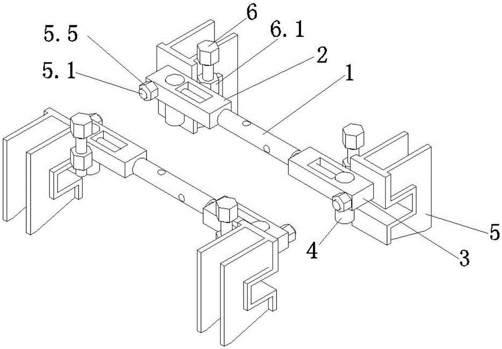
[0038] Taking the butt joint of steel beam one 7 and steel beam two 8 as an example, the present invention provides a method for positioning and installing an H-shaped steel beam joint joint, which specifically includes the following steps:

[0039] Step 1. Pre-install the connecting plate 10 through the hinge 9 on both sides of the web of the steel beam 7. A part of the connecting plate 10 overlaps with the web of the steel beam 7. The bolt holes opened on the connecting plate 10 are aligned with the steel beam. - Alignment of the bolt holes opened on the web;

[0040] Step 2: Lift steel beam 1 7 to the steel beam 2 8 with lifting equipment for docking. 8 There is a gap of 5~10mm between the butt ends; at the same time, the connecting plate 10 is unfolded, and the other part of the connecti...


PUM


Abstract

The invention discloses a locating and mounting method for H-shaped steel girder butting joints. The locating and mounting method specifically comprises the following steps: pre-assembling connection plates on two sides of a web plate of a steel girder I; hoisting and conveying the steel girder I to a steel girder II for butting; providing a locating and mounting device; mounting an adjustment mechanism; mounting a clamping mechanism; aligning bolt holes in the connection plates and the steel girder II; inserting high-strength bolts into the bolt holes in the connection plates and the web plates of the two steel girders to realize connection between the connection plates and the web plates of the two steel girders; removing the locating and mounting device, arranging a top plate on the surfaces of flanges of the steel girder I and the steel girder II, correspondingly forming bolt holes in the top plate and the flanges of the steel girder I and the steel girder II, and connecting the top plate to the steel girder I and the steel girder II through high-strength bolts. The locating and mounting method has the benefits that by the adoption of the adjustment structure and the clamping mechanism which are combined, the transverse staggering and the longitudinal staggering of the bolt holes in the connection plates and the web plates of the steel girders can be eliminated, so that the bolt holes can be quickly aligned to realize temporary fixing for butting of two H-shaped steel girder butting joints, and preparation can be made for the subsequent connection and mounting procedures.

Description

technical field [0001] The invention relates to steel structure installation, in particular to a method for positioning and installing an H-shaped steel beam butt joint node. Background technique [0002] The installation of steel structures usually involves the installation of various steel beams and supports. The installation of this stage is characterized by small unit weight, large installation base, many steps, and takes a long time. At present, the installation of steel girders and supports and other structures are usually hoisted by hoisting machinery, and then the installers are responsible for the structural connection and fixing. Due to the long cycle of hoisting, positioning and connection of the steel structure, the hoisting machinery is in a stagnant state during this period, and the fast and efficient characteristics of the hoisting machinery cannot be fully utilized. This not only increases the cost of using the crane in construction, but also restricts the in...

Claims


Application Information

Patent Timeline
Patent Type & Authority Applications(China)
IPC IPC(8): E04G21/14E04G21/18E04B1/24E04B1/58
CPCE04B1/2403E04B2001/2415E04B2001/2418E04G21/14E04G21/1841
Inventor 吴钢刘斌唐明丰田红云郭继舟李少祥夏春吴旭管安康
Owner CHINA FIRST METALLURGICAL GROUP
Why Eureka
Try Eureka