Actuating device

A technology for actuating equipment and equipment, which is applied in the direction of mechanical equipment, engine components, combustion engines, etc., can solve expensive and technically complex problems, and achieve the effect of eliminating complicated and expensive welding

Inactive Publication Date: 2016-12-07
BOSCH MAHLE TURBO SYST GMBH & CO KG
View PDF1 Cites 0 Cited by
  • Summary
  • Abstract
  • Description
  • Claims
  • Application Information

AI Technical Summary

Problems solved by technology

Here the connecting element is welded to the holding element, which is technically complex and expensive

Method used


Image

  • Actuating device
  • Actuating device
  • Actuating device

Examples


Embodiment Construction

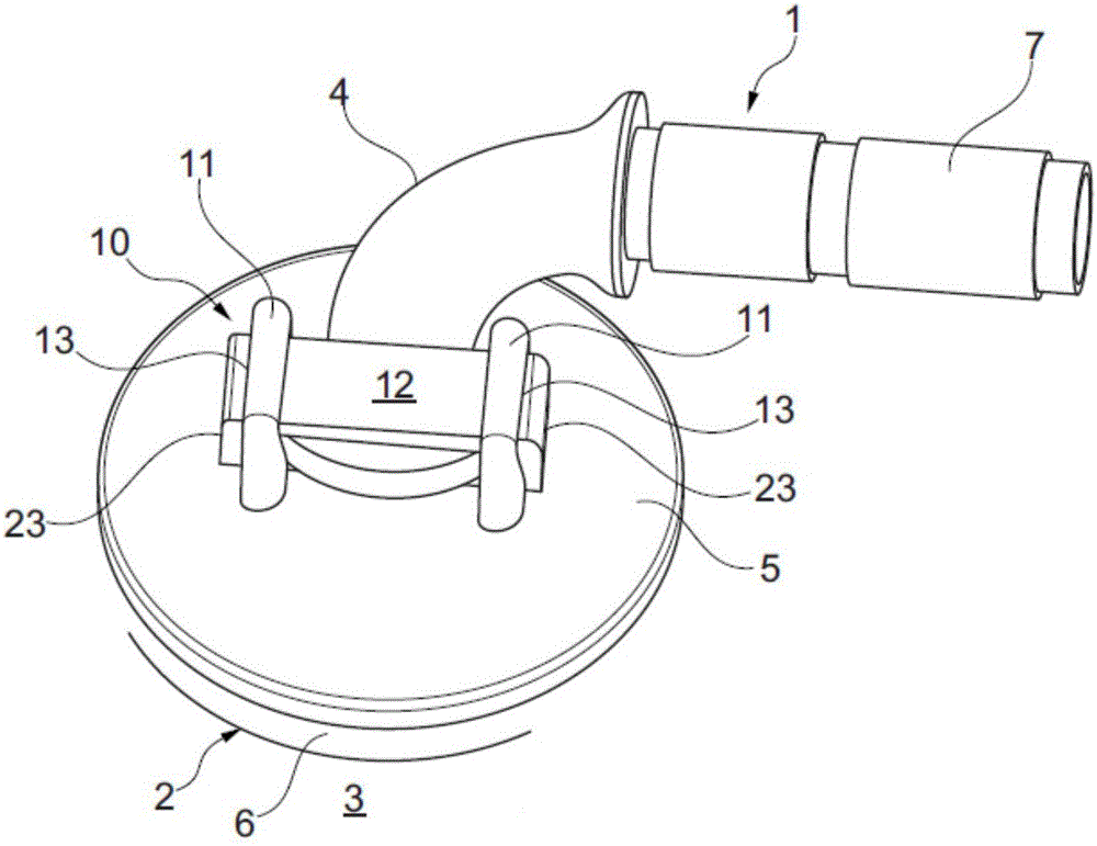
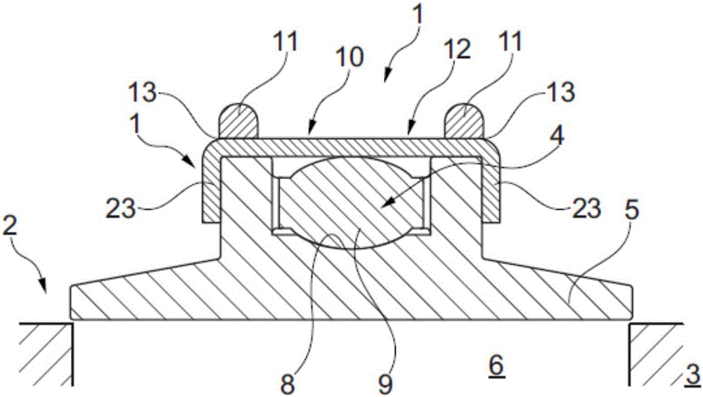
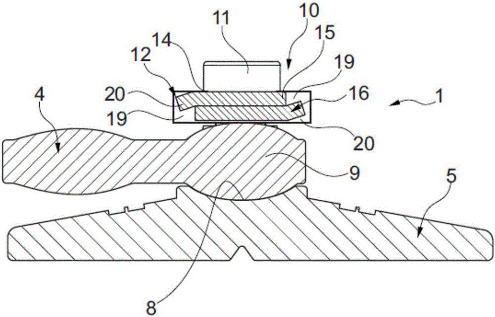
[0025] according to Figure 1 to Figure 3 as well as Image 6 with Figure 7 , according to the invention for an actuating device 1 for a valve 2 , in particular for a wastegate valve for an exhaust gas turbocharger 3 , having a lever arm 4 and a plate connected thereto for closing the opening 6 of the valve 2 5. Here the lever arm 4 is attached to the spindle 7 of the actuating device 1 . The plate 5 has a concave groove 8, while the lever arm 4 has a spherical area 9 formed in a complementary manner with respect to the concave groove 8 of the plate 5, and with which the lever arm engages in the concave shape of the plate 5. in groove 8. Furthermore, a holding device 10 with two holding elements 11 and a connecting element 12 connecting the holding elements 11 is provided on the plate 5, said holding device engaging around the spherical area 9 of the lever arm 4, as a result, fixing the plate 5 on the bar on arm 4.

[0026] In order to be able to configure the component...


PUM


Abstract

The invention relates to an actuating device (1) for a valve (2), in particular for a wastegate valve of an exhaust-gas turbocharger (3). The actuating device (1) may include a lever arm (4) and a flap plate (5) connected to one another for closing and opening the valve (2). A holding device (10) is arranged on the flap plate (5), and fixes the flap plate (5) on the lever arm (4). Each holding element (11) has a passage opening (13) through which a connecting element (12) is guided, wherein longitudinal ends (23) of the connecting element (12) are bent over and thus secure the connecting element (12) on the flap plate (5), or the holding elements (11) are of pin-shaped design and each have a circumferential groove 14, wherein the connecting element (12) has two subelements (15 and 16) each having a longitudinal groove (17) and a transverse groove (18) and engage by means of their respective longitudinal groove (17) in the circumferential groove (14) of the one holding element (11) and by means of their transverse groove (18) in the circumferential groove (14) of the other holding element (11).

Description

technical field [0001] The invention relates to an actuation device for a valve, in particular for a wastegate valve of an exhaust gas turbocharger, according to the preamble of claim 1 . Furthermore, the invention relates to an exhaust gas turbocharger with a wastegate and an actuation device of this type. Background technique [0002] In conclusion, modern exhaust gas turbochargers are equipped with electric or pneumatic actuators which are required for adjusting the valve arrangement on the turbine (waste grid). The actuator is activated via a motor-actuation control thereby moving the control rod. A generally linearly moving control rod acts on a lever arm that converts the movement into rotation and at the same time transmits the rotation to the plate. These dynamics ensure that mass flow is controlled by the wastegate. But for the dynamics to work, without friction, all parts must have minimal play and must move freely. Minimum play is also required to compensate f...

Claims


Application Information

Patent Timeline
Patent Type & Authority Applications(China)
IPC IPC(8): F02B37/18
CPCF02B37/186F02B37/183F16K1/20F16K1/36F16K51/00Y02T10/12F16K1/18F16K1/32F16K31/44
Inventor 约亨·格克勒曼阿纳托利耶·马腾斯蒂莫·特里斯
Owner BOSCH MAHLE TURBO SYST GMBH & CO KG
Why Eureka
Try Eureka