Apparatus and method for providing communication between a probe and a sensor

a technology of applied in the field of apparatus that provides communication between a probe and a sensor, can solve the problems of difficult wired connection, strong influence of lwd sensors and some of the newer generation mwd sensors, etc., to achieve a larger tolerance of axial alignment of the two antennas, reduce axial misalignment sensitivity, and simple and cleaner field tool make-up

Active Publication Date: 2006-12-28
ULTIMA LABS
View PDF12 Cites 32 Cited by
  • Summary
  • Abstract
  • Description
  • Claims
  • Application Information

AI Technical Summary

Benefits of technology

[0014] As noted earlier, since the probe and sensor electronics are located in separate sealed pressure housings, a wired connection between them is problematic. An advantage of the present invention is that it allows bi-directional transfer of data between the probe and sensor electronics without the use of wires. The wireless communication link overcomes the prior art problems and eliminates the complexities of connecting wires between the probe and the collar electronics in the field.
[0015] Another advantage is that the disclosed method and apparatus allows a simple and cleaner field tool make-up, and wherein no wired connections are required to be made in the field. Also, another advantage of the disclosed method is a decreased sensitivity to axial misalignment of the probe inside the collar bore when the axial length of one of the antennas is extended to provide larger tolerance of axial alignment of the two antennas. Yet another advantage is that no pressure feed-thrus are required to route wiring between the probe and the collar.
[0016] A feature of the present invention is that the apparatus uses electromagnetic radiation to establish the communication link. Another feature is that the probe and drill-collar instrumentation are in completely separate pressure containers reducing the risk of flooding both devices should one pressure container develop a leak. Yet another feature is that there are fewer mechanical intrusions into the fluid flowing through the center of the drill collar.

Problems solved by technology

However, some of the LWD sensors and some of the newer generation MWD sensors can be strongly affected by the surrounding drill collar and have to be located in the external wall of the drill collar.
However, wired connections are very problematic.

Method used


Image

  • Apparatus and method for providing communication between a probe and a sensor
  • Apparatus and method for providing communication between a probe and a sensor
  • Apparatus and method for providing communication between a probe and a sensor

Examples


Embodiment Construction

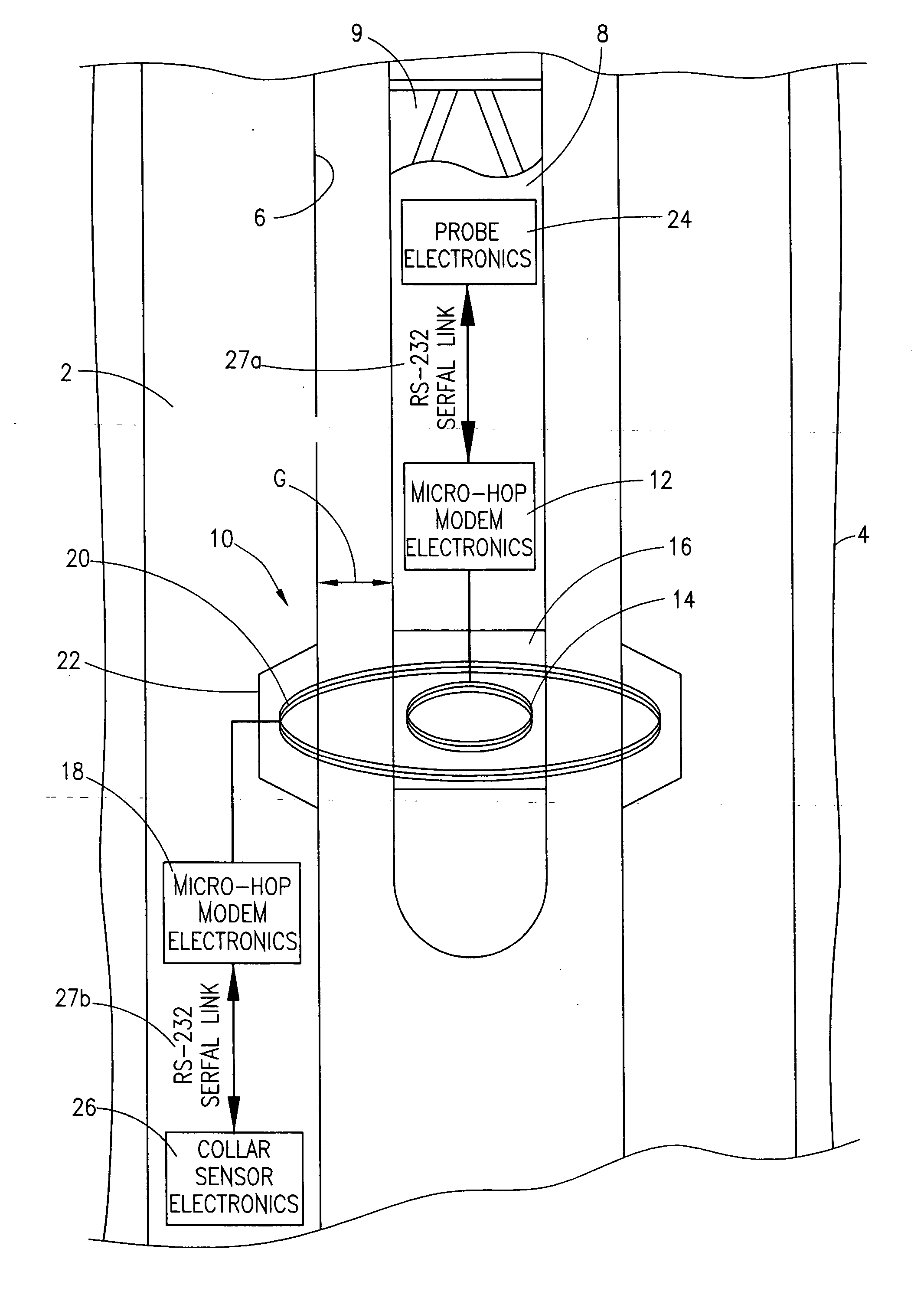
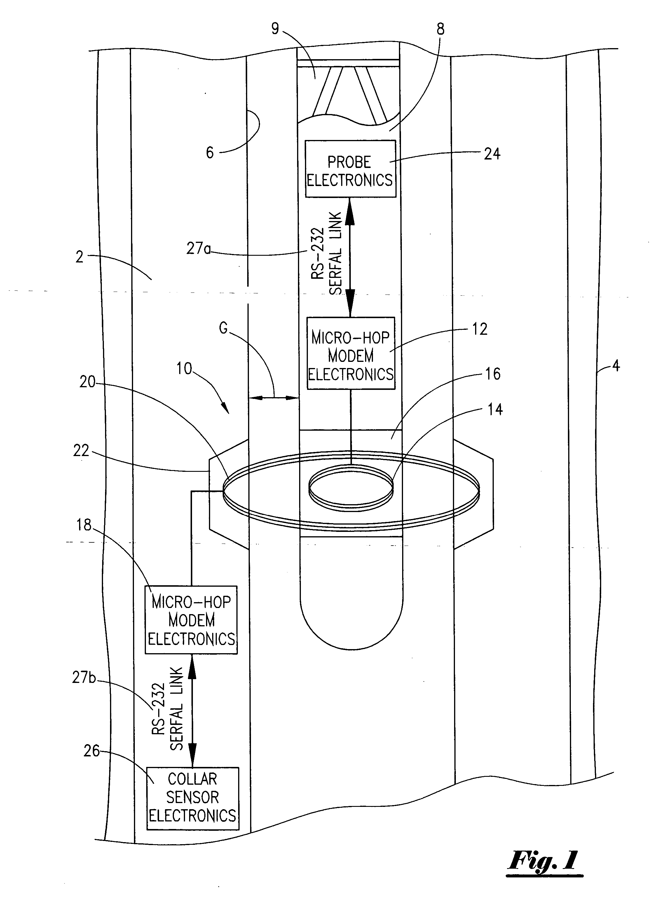
[0032] Referring now to FIG. 1, a perspective block diagram of the most preferred embodiment of the present invention will now be described. As shown in FIG. 1, a tubular member 2, such as a drill collar, is disposed within a well bore 4. The drill collar 2 has an internal diameter portion 6, and wherein the probe 8, which is generally cylindrical, is slidably disposed within the internal diameter portion 6. The drill collar 2 may be connected to a drill bit used for boring a bore hole. The probe 8 may be operatively associated with a MWD tool or LWD tool (not shown). As those of ordinary skill in the art will appreciate, the MWD tool can create a pressure pulse that duplicates a digital code transmission thereby allowing the transmission of down hole data to the surface. MWD and LWD tools are commercially available from Baker Hughes Inc. It should also be noted that the probe 8 may be connected via a hard wired cable, known in the industry as electric line, and wherein the transmis...


PUM


Abstract

A wireless data communication system for a down hole environment. The system includes a housing containing a sensor, positioned within a tubular, for collecting information and processing the information, a modulator for modulating the information from the sensor into an analog signal, and a sensor antenna electrically connected to the first modulator for generating a modulated electromagnetic wave. The system further includes a probe housing, concentrically disposed within the tubular, comprising a probe antenna for receiving the modulated electromagnetic wave and generating an output, and a demodulator for demodulating the electromagnetic wave received from the sensor to a digital record. A method of wirelessly communicating between a probe and a remote sensor is also disclosed.

Description

BACKGROUND OF THE INVENTION [0001] This invention relates to an apparatus that provides communication between a probe and a sensor. More particularly, but not by way of limitation, this invention relates to an apparatus and method that provides communication between a probe located in the central bore of a drill collar and sensor electronics located in the drill collar wall. [0002] In the course of drilling wells, an operator finds it necessary to learn geologic properties of the subterranean zones. Regardless of whether the zones contain hydrocarbons, the knowledge of specific features and characteristics of the various reservoirs is imperative for the economical exploitation of a field. One way to obtain geologic information of the formation is to lower a probe on a wire line. The probe may contain various sensors such as resistivity, gamma ray, gamma density, neutron porosity, pressure, etc. As those of ordinary skill in the art will recognize, the probes may be lowered in open h...

Claims


Application Information

Patent Timeline
Patent Type & Authority Applications(United States)
IPC IPC(8): G01V3/00
CPCG01V11/002E21B47/13
Inventor FLANAGAN, WILLIAM D.
Owner ULTIMA LABS
Why Eureka
Try Eureka