Quick exhaust device for automobile oil way and use method of quick exhaust device

A technology of exhaust device and automobile oil circuit, which is applied in the direction of fuel injection device, electrical control, charging system, etc., which can solve the problems of long start-up time for the first time of a new car and affect the off-line of the new car, and achieve a reasonable and novel structural design and speed up the process of getting off the assembly line. Line beats, the effect of increasing costs

Inactive Publication Date: 2016-12-07
HARBIN DONGAN AUTOMOTIVE ENGINE MFG CO LTD
View PDF5 Cites 6 Cited by
  • Summary
  • Abstract
  • Description
  • Claims
  • Application Information

AI Technical Summary

Problems solved by technology

[0002] When a new car is not filled with fuel, there must be air in the fuel pipeline. After the fuel is added from the fuel tank filling port for the first time, when the car is started, the fuel is supplied to the engine through the fuel pump in the fuel tank, and the fuel must be filtered in the middle. A long and thin fuel line, fuel rail to the injector, because there is air in the fuel line of a new car, the air in this part must be discharged at the beginning of the vehicle start, before the fuel can reach the injector. The injector sprays air, the engine cannot be ignited, and the vehicle cannot be started. It takes a long time for the fuel to reach the injector. This situation leads to a long time for the new car to start for the first time, which affects the new car off the assembly line.

Method used


Image

  • Quick exhaust device for automobile oil way and use method of quick exhaust device
  • Quick exhaust device for automobile oil way and use method of quick exhaust device
  • Quick exhaust device for automobile oil way and use method of quick exhaust device

Examples


Embodiment 1

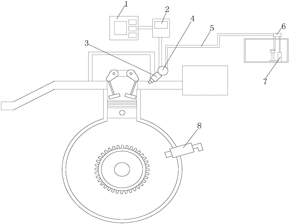
[0036] The invention relates to an automobile oil circuit quick exhaust device, comprising an engine, the engine is connected with the engine oil circuit, an instruction issuing device, the instruction issuing device is connected with an electronic control unit, the electronic control unit is connected with a fuel injector, and the fuel injector is connected with a The oil rail is arranged on the engine oil circuit; the engine is provided with a rotational speed sensor, and the rotational speed sensor is connected to the electronic control unit; the oil rail is connected to the fuel filter and the oil pump through the engine oil circuit.

[0037] A method for using a quick exhaust device for an automobile oil circuit is made by the following steps:

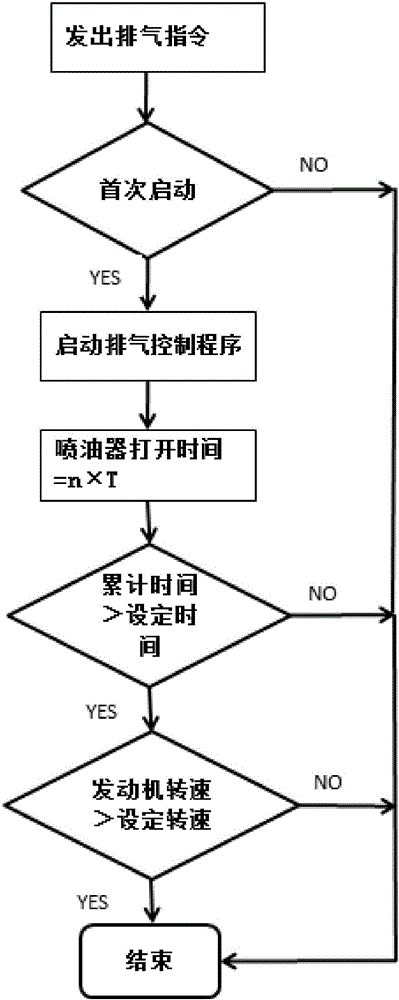
[0038] (1) The instruction issuing equipment on the engine production line issues the exhaust instruction. After receiving the exhaust instruction, the electronic control unit determines whether the vehicle is started for the first...

Embodiment 2

[0050] The difference between this embodiment and Embodiment 1 is that: in step (4), it is determined whether the air in the engine oil circuit is emptied by detecting whether the accumulated exhaust time is greater than the set exhaust time.

[0051] The calculation formula of the exhaust cumulative time is:

[0052] Exhaust cumulative time t=V 总 / (Q×n×T÷1000×m)

[0053] where: V 总 =V 滤清器 +V 管 +V 油轨 +V 喷油器

[0054] Q--fuel injection volume per unit time, unit ml / s;

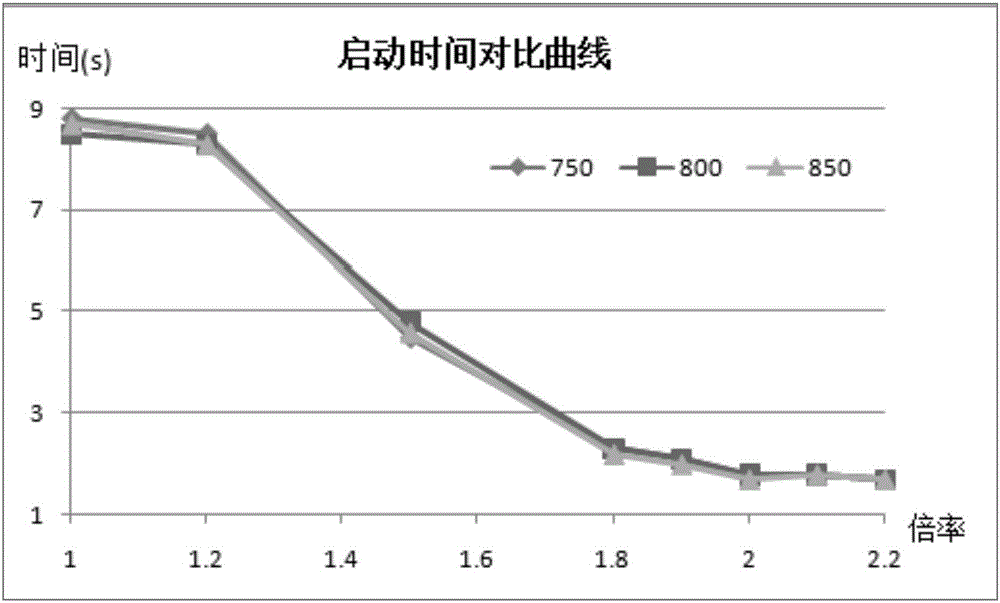
[0055] n--Injector opening time magnification (for fast exhaust, n>1), hereinafter referred to as "magnification"

[0056] T--Injector single opening time, unit: ms, this parameter is a parameter in the normal fuel injection program, and is related to the engine water temperature;

[0057] m--the total opening times of the injectors of each cylinder;

[0058] V is the total volume of the engine oil circuit cavity;

[0059] V filter is the volume of the inner cavity of the filter;

[0060] The V tube is...


PUM


Abstract

The invention discloses a quick exhaust device for an automobile oil way. The quick exhaust device for the automobile oil way comprises an engine and an instruction sending-out device. The engine is connected with an engine oil way, the instruction sending-out device is connected with an electronic control unit, the electronic control unit is connected with an oil atomizer, the oil atomizer is connected with an oil rail, and the oil rail is arranged on the engine oil way. The engine is provided with a rotation speed sensor, and the rotation speed sensor is connected with the electronic control unit. The oil rail is connected with a fuel filter and an oil pump through the engine oil way. The quick exhaust device has the beneficial effects that the defects of the prior art can be overcome, and the structural design is reasonable and novel.

Description

technical field [0001] The invention relates to a rapid exhaust device for an automobile oil circuit and a method for using the same, belonging to the field of automobile manufacturing. Background technique [0002] When the newly produced car is not filled with fuel, there must be air in the fuel line. After the fuel is added from the fuel injection port of the fuel tank for the first time, when the car is started, the fuel is supplied to the engine through the fuel pump in the fuel tank, and the fuel must be filtered in the middle. In the early stage of vehicle startup, this part of the air must be exhausted before the fuel can reach the injector, and the fuel is injected for a period of time at the beginning. The injector sprayed air, the engine could not be ignited, the vehicle could not be started, and it took a long time for the fuel to reach the injector. SUMMARY OF THE INVENTION [0003] In view of the deficiencies in the prior art, the technical problem to be sol...

Claims


Application Information

Patent Timeline
Patent Type & Authority Applications(China)
IPC IPC(8): F02M55/00F02D41/30F02M37/00
CPCF02M55/007F02D41/30F02M37/00
Inventor 马南王建武潘圣临曹权佐蔡昊李杨刘顺平刘金铸赵鹤宇曹亮于荣枫马江涛胡志刚闫立君赵长明李杰
Owner HARBIN DONGAN AUTOMOTIVE ENGINE MFG CO LTD
Why Eureka
Try Eureka