Air cylinder type vacuum pump

A vacuum pump, cylinder type technology, applied in the direction of pump components, rotary piston type/oscillating piston type pump components, components of pumping devices for elastic fluid, etc., can solve the problems of occupying engine output power and energy waste, etc. Achieve the effect of reducing load, saving energy consumption, and controlling the working state

Active Publication Date: 2016-12-07
SHANGHAI ZHAOMIN POWER TECH CO LTD
View PDF5 Cites 1 Cited by
  • Summary
  • Abstract
  • Description
  • Claims
  • Application Information

AI Technical Summary

Problems solved by technology

After that, the continuous operation of the vacuum pump will occu

Method used


Image

  • Air cylinder type vacuum pump
  • Air cylinder type vacuum pump
  • Air cylinder type vacuum pump

Examples


Embodiment approach 1

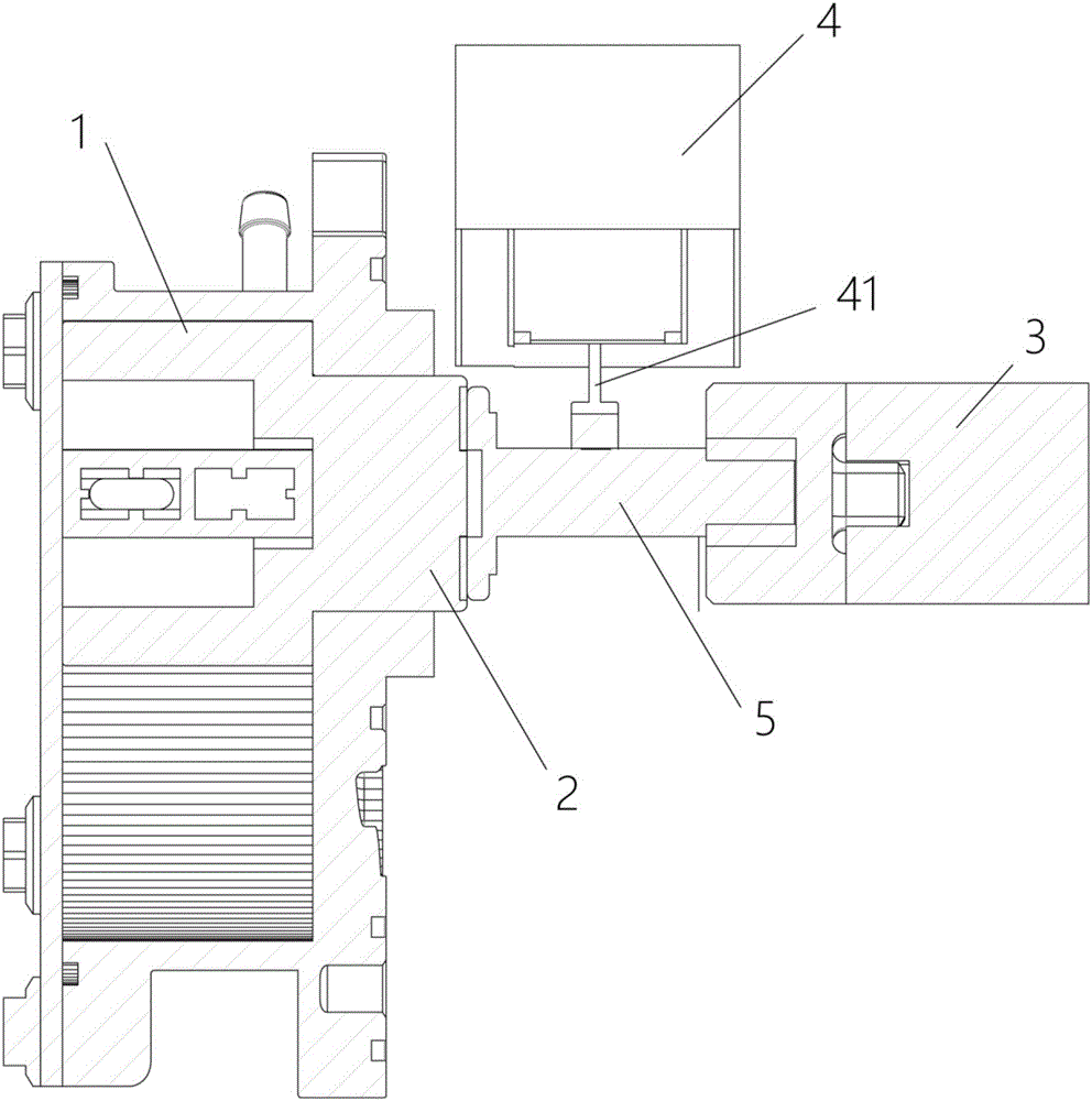
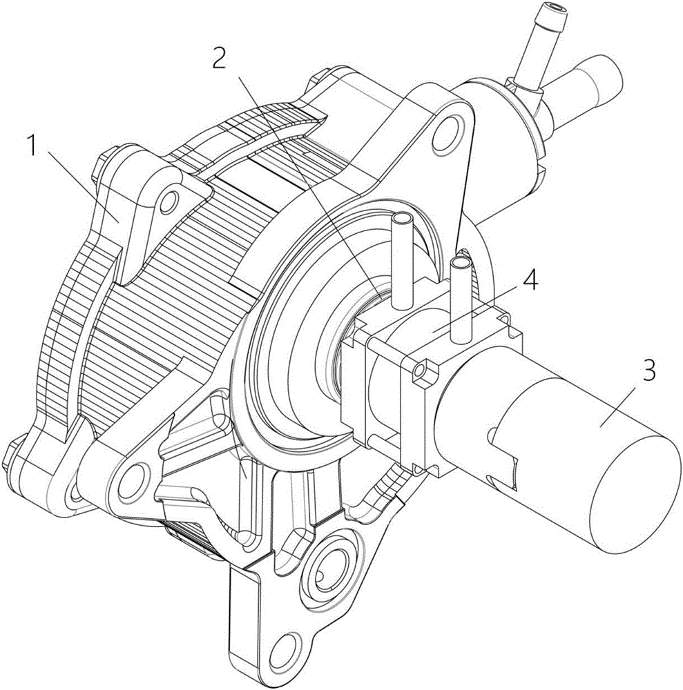
[0034] The first embodiment of the present invention provides a cylinder type vacuum pump, see figure 1 As shown, it includes a pump body 1 and a power input shaft 2 protruding from the pump body 1; the power input shaft 2 is set opposite to the power transmission shaft 3 extending from the external power mechanism; the power transmission shaft 3 rotates on its own axis Axis rotation.

[0035] In addition, the cylinder-type vacuum pump also includes a cylinder 4, which is used to control the connection or separation of the power transmission shaft 3 and the power input shaft 2; when the power transmission shaft 3 is connected with the power input shaft 2, the power transmission shaft 3 drives the power input shaft 2 to rotate , the cylinder vacuum pump works; when the power transmission shaft 3 is separated from the power input shaft 2, the cylinder vacuum pump stops working.

[0036] Specifically, in this embodiment, see figure 1 As shown, the cylinder type vacuum pump incl...

Embodiment approach 2

[0044] In the present invention, there are many ways for the cylinder 4 to push the clutch block 5 to move. In the first embodiment, the push rod protruding from the external cylinder 4 is used as an example for illustration.

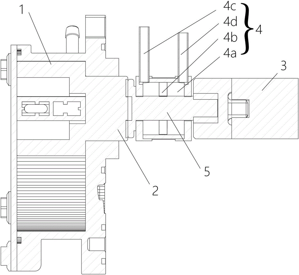
[0045] The second embodiment of the present invention provides a cylinder type vacuum pump, the second embodiment is a further improvement of the first embodiment, the main improvement is that, in the second embodiment of the present invention, see figure 2 , image 3 As shown, the clutch block 5 is at least partially located inside the cylinder 4 .

[0046] Specifically, the cylinder 4 includes a housing formed with a cavity 4a and a partition 4b disposed in the cavity 4a.

[0047] At least part of the clutch block 5 is located in the cavity 4a, and is connected with the partition 4b. The partition 4b divides the cavity 4a into two sub-cavities along the axial direction of the power input shaft 2, which are respectively the left cavity and the right ...

Embodiment approach 3

[0055] In the second embodiment of the present invention, the contact relationship between the partition 4b and the inner wall of the cavity 4a is not limited. In actual use, the space between the partition 4b and the inner wall of the cavity 4a is airtight In contact with the ground, the partition 4b can move flexibly.

[0056] The third embodiment of the present invention provides a cylinder type vacuum pump, the third embodiment is a further improvement of the second embodiment, the main improvement is that, in the third embodiment of the present invention, see Figure 4 As shown, a bearing 6 is also provided on the partition 4b. Using the bearing 6 to counteract the possible rotational movement of the partition 4b can effectively prevent the possible friction of the partition 4b against the inner wall of the cavity 4a and prolong the service life of the partition 4b.

[0057] In this embodiment, the spacer 4b may be a piston or a plastic spacer, etc., to achieve the isola...


PUM


Abstract

The invention relates to the technical field of automobile vacuum, and discloses an air cylinder type vacuum pump. The air cylinder type vacuum pump comprises a pump body and a power input shaft stretching out of the pump body. The power input shaft is opposite to a power transmission shaft extending out of an external power mechanism. The power transmission shaft rotates with the axis of the power transmission shaft as the rotating axis. In addition, the air cylinder type vacuum pump comprises an air cylinder. The air cylinder is used for controlling connection or separation of the power transmission shaft and the power input shaft. When the power transmission shaft and the power input shaft are connected, the power transmission shaft drives the power input shaft to rotate, and the air cylinder type vacuum pump works. When the power transmission shaft and the power input shaft are separated, the air cylinder type vacuum pump stops working. The air cylinder type vacuum pump can be started and stopped according to actual needs, and is fast and accurate in control, lower in energy consumption and longer in service life.

Description

technical field [0001] The invention relates to the technical field of vehicle vacuum, in particular to a cylinder type vacuum pump. Background technique [0002] Vacuum pumps can be used in various fields. For example, for vacuum pumps used in automobile brake systems, there are various forms of vacuum pumps such as diaphragm type, rotary vane type, and clutch block type. Among them, the application of rotary vane type is the most universal. [0003] In the rotary vane vacuum pump, the rotor and the stator are installed eccentrically in the pump. The rotor is tangent to the fixed surface of the stator. The rotor is connected to the external power mechanism through the power input shaft, and is driven by the external power mechanism with its own axis as the The axis of rotation rotates. Driven by this rotary motion, two or more rotating vanes rotate in the rotor slot and contact with the inner wall of the stator to divide the pump chamber into several variable volumes, so ...

Claims


Application Information

Patent Timeline
IPC IPC(8): F04C29/00F16D25/08
CPCF04C29/005F16D25/082F16D25/083
Inventor 李回城柳智平沈新峰郑昌春
Owner SHANGHAI ZHAOMIN POWER TECH CO LTD
Why Eureka
Try Eureka