Supercharge Your Innovation With Domain-Expert AI Agents!

Pipeline compensator used for catalytic cracking equipment

A pipeline compensator and catalytic cracking technology, which is applied in the expansion compensation device for pipelines, pipeline protection, mechanical equipment, etc., can solve the problems that cannot completely solve the adverse effects of metal bellows, affect the working performance and service life of compensators, etc. , to achieve the effect of solving adverse effects, prolonging the service life and ensuring reliable operation

Active Publication Date: 2016-12-07
彭钢永
View PDF7 Cites 0 Cited by
  • Summary
  • Abstract
  • Description
  • Claims
  • Application Information

AI Technical Summary

Problems solved by technology

Coking formed in the compensation bellows will seriously affect the working performance and service life of the compensator
In order to solve the problems caused by the pipeline conveying medium entering the compensation bellows, including the prior patent applications CN200993293Y and CN205208017U, the pipeline compensator has been improved in various forms, but none of them can completely solve the problem of the pipeline conveying medium on the metal corrugated pipe. Adverse effects of the tube

Method used


Image

  • Pipeline compensator used for catalytic cracking equipment
  • Pipeline compensator used for catalytic cracking equipment

Examples


Embodiment Construction

[0011] The specific implementation manner of the present invention will be described below in conjunction with the accompanying drawings and embodiments.

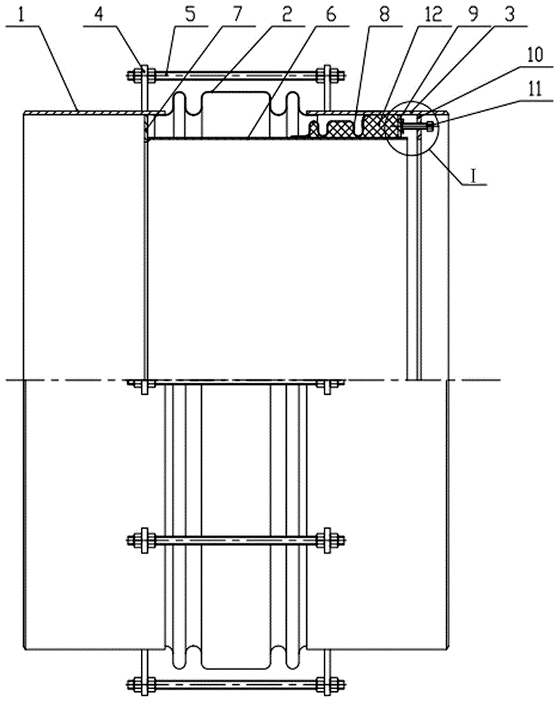
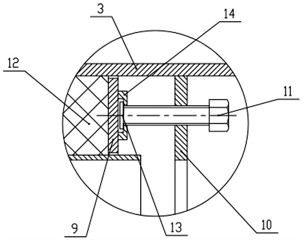
[0012] figure 1 The specific structure of the pipeline compensator used in this catalytic cracking equipment is given, which includes a front-end joint 1, a compensation bellows 2 and a rear-end joint 3 connected in sequence from front to back. The front-end joint 1 and the rear-end joint 3 have the same Inner and outer pipe diameters, the compensation bellows 2 are metal bellows. The front-end connecting pipe 1, the compensation bellows 2 and the rear-end connecting pipe 3 are respectively connected by welding. The opposite ends of the front-end connecting pipe 1 and the rear-end connecting pipe 3 are respectively welded with lugs 4 distributed along the circumference, and the two opposite lugs 4 are assembled with bolt pull rods 5, such as figure 1 In an embodiment, the two sides of each ear plate 4 are respectively equ...


PUM


Abstract

A pipeline compensator used for catalytic cracking equipment comprises a front-end connecting pipe, a compensation corrugated pipe and a rear-end connecting pipe which are sequentially connected, wherein lug plates are distributed on the front-end connecting pipe and the rear-end connecting pipe, and bolt pull rods are assembled on the lug plates; a flow guiding cylinder is arranged in the compensation corrugated pipe, the flow guiding cylinder is connected with the front-end connecting pipe through a connecting ring plate of the flow guiding cylinder, the outer side of the flow guiding cylinder is provided with a blocking corrugated pipe, the front end of the blocking corrugated pipe is connected with the flow guiding cylinder, and the rear end of the blocking corrugated pipe is connected with the rear-end connecting pipe; a sealing ring plate is arranged between the rear-end connecting pipe and the flow guiding cylinder, a limiting flange is arranged in the rear-end connecting pipe, axial jacking screws are distributed on the limiting flange, and each axial jacking screw is in rotatable connection with the sealing ring plate; and an annular sealed cavity is formed by the rear-end connecting pipe, the blocking corrugated pipe, the flow guiding cylinder and the sealing ring plate, and the annular sealed cavity is filled with high-temperature-resistant fibers. The pipeline compensator can prevent the forming of coking in the corrugated pipes and meet the work requirements of the existing catalytic cracking equipment. The reliable work of the pipeline compensator is ensured, and the service life is prolonged.

Description

technical field [0001] The invention relates to a pipeline compensator, in particular to a pipeline compensator used in catalytic cracking equipment. Background technique [0002] Oil and gas pipelines of catalytic cracking equipment in refineries need to be equipped with pipeline compensators to compensate for thermal elongation of pipelines. At present, the pipeline compensator used in catalytic cracking equipment is generally a metal bellows compensator with a guide tube inside. There is a gap between the guide tube and the rear end of the compensator. During the working process, the medium in the pipeline Entry into the compensating bellows through this gap can cause coke formation in the compensating bellows. Coking formed in the compensation bellows will seriously affect the performance and service life of the compensator. In order to solve the problems caused by the pipeline conveying medium entering the compensation bellows, including the prior patent applications ...

Claims


Application Information

Patent Timeline
IPC IPC(8): F16L51/02F16L59/21
CPCF16L51/02F16L59/21
Inventor 彭刚福屠永强袁华俊
Owner 彭钢永
Features
  • R&D
  • Intellectual Property
  • Life Sciences
  • Materials
  • Tech Scout
  • Unparalleled Data Quality
  • Higher Quality Content
  • 60% Fewer Hallucinations
Learn More