Consumable chip and its data resetting method, consumable container

A consumable chip and data technology, applied in the field of consumable containers, can solve problems such as affecting the work of the toner cartridge laser printer, unable to cover the toner remaining data in time, etc., and achieve the effect of ensuring timeliness and accuracy and ensuring stability

Inactive Publication Date: 2012-06-27
ZHUHAI TIANWEI TECH DEV CO LTD
View PDF7 Cites 18 Cited by
  • Summary
  • Abstract
  • Description
  • Claims
  • Application Information

AI Technical Summary

Problems solved by technology

Moreover, the other side of the substrate is provided with an electronic module and a light-emitting diode that are electrically connected to the electrical contact 34, and the electronic module is provided with a control unit and a memory, etc. For the same reason, the chip 33 also has a predetermined value of remaining carbon powder. The problem that data cannot be written into the first storage area in time and overwrite the original toner remaining data

Method used


Image

  • Consumable chip and its data resetting method, consumable container
  • Consumable chip and its data resetting method, consumable container
  • Consumable chip and its data resetting method, consumable container

Examples


no. 1 example

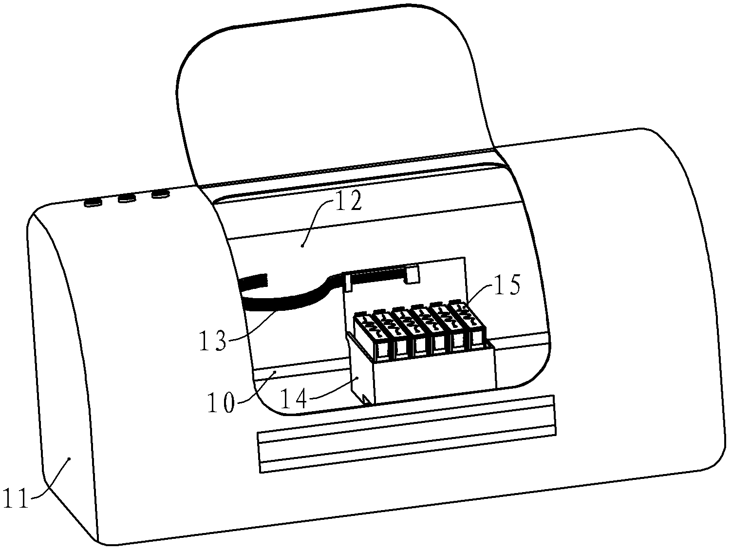
[0040] The consumable chip in this embodiment is an ink cartridge chip installed in an ink cartridge for an inkjet printer, which has a substrate, and one side of the substrate is provided with a plurality of electrical contacts as a communication unit for connecting with the electrical contacts of the inkjet printer. Of course, if the inkjet printer and the chip of the consumables communicate wirelessly, the communication unit is an antenna for wireless communication. On the other side of the substrate, there are electronic modules and light-emitting diodes connected to electrical contacts. The electrical schematic diagram of the connection between the electronic modules and the light-emitting diodes is as follows Figure 5 shown.

[0041] The electronic module 40 is provided with a control unit 41 , a memory 42 and a counter 48 , wherein the memory 42 is provided with a first storage area 43 and a second storage area 44 . The first storage area 43 stores data related to ink...

no. 2 example

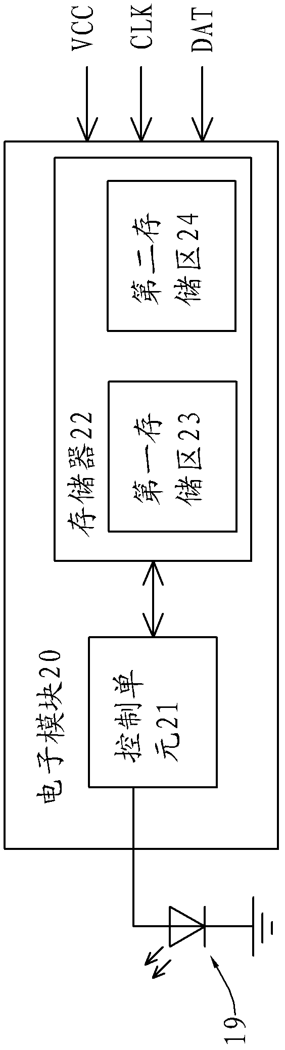
[0050] This embodiment has a substrate on which electrical contacts, electronic modules, and light-emitting diodes are arranged. The electrical schematic diagram of the connection between the electronic module and the light-emitting diodes is as follows Figure 6 shown. The electronic module 50 is provided with a control unit 51 and a memory 52. ​​The memory 52 has a first storage area 53 and a second storage area 54. The first storage area 53 stores ink remaining data, and the second storage area stores a predetermined ink remaining value. data. The anode of the LED 56 is connected to the electronic module 50 and the cathode is grounded.

[0051] The control unit 51 receives signals from the inkjet printer, including a clock signal CLK, a data signal DAT, and the like. In addition, the control unit 51 also receives a control signal from the inkjet printer, and sends an on-off signal SCK to the anode of the light-emitting diode 56 . When the inkjet printer is working normal...

no. 3 example

[0057] This embodiment is also provided with a substrate, and the substrate is provided with electrical contacts, electronic modules, and light-emitting diodes. The electrical schematic diagram of the connection between the electronic module and the light-emitting diodes in this embodiment is the same as that of the second embodiment, and will not be repeated here.

[0058] In this embodiment, when the inkjet printer is working normally, the frequency of the on-off signal sent by the control unit to the light-emitting diode is relatively low, and when the ink remaining data is judged to be low, the frequency of the on-off signal is relatively high. larger. Therefore, when the counter judges that the count value is greater than the threshold value, the first signal sent to the control unit is a data reset signal. After the control unit receives the data reset signal, it will write the predetermined value data of the remaining ink level stored in the second storage area. Go to t...


PUM


Abstract

The invention provides a consumable chip and its data resetting method, as well as a consumable container. The chip comprises an electronic module and a light-emitting diode. The electronic module is provided with a control unit and a memory, which includes a first storage area and a second storage area. Consumable margin data are stored in the first storage area, and consumable margin predetermined value data are stored in the second storage area. At least one pin of the light-emitting diode is in connection with the electronic module, wherein, the electronic module is also provided with a data resetting unit. The method comprises that: the data resetting unit receives the on-off signal of the light-emitting diode, and judges whether the frequency of the on-off signal is higher or lower than a set value, if so, the resetting unit sends a data resetting signal to the control unit, which, after receiving the data resetting signal, writes the consumable margin predetermined value data stored in the second storage area into the first storage area to cover the consumable margin data. The consumable chip of the invention can ensure that the consumable margin predetermined value data can be written into the first storage area timely and guarantee stable working of the consumable container.

Description

technical field [0001] The invention relates to the field of printing, in particular to a consumable chip mounted on a printing consumable, a data reset method for the chip, and a consumable container equipped with the consumable chip. Background technique [0002] As a common office equipment, printers provide great convenience for modern office. Existing printers are divided into inkjet printers and laser printers. Inkjet printers use ink cartridges containing ink as consumable containers to spray ink on paper to form text or patterns that need to be printed on paper; laser printers use ink cartridges containing toner The toner cartridge is used as a consumable container to form text or patterns that need to be printed on the medium. [0003] see figure 1 , an existing color inkjet printer has a casing 11, figure 1 The inkjet printer is shown with the chassis 11 omitted. The machine core 12 of ink-jet printer is provided with in the casing 11, and is provided with a sl...

Claims


Application Information

Patent Timeline
IPC IPC(8): G11C7/22B41J2/175G03G15/08
Inventor 袁珍平
Owner ZHUHAI TIANWEI TECH DEV CO LTD
Why Eureka
Try Eureka