Backlight Module

A technology of backlight module and light source, which is applied in the field of backlight module, can solve problems such as blue light leakage or blue halo, affecting picture quality, light leakage, etc., and achieve the effects of reducing light leakage, improving edge bluishness, and increasing the number of reflections

Active Publication Date: 2019-12-31
CORETRONIC
View PDF13 Cites 0 Cited by
  • Summary
  • Abstract
  • Description
  • Claims
  • Application Information

AI Technical Summary

Problems solved by technology

Because the backlight module 100 has an edge with a narrow frame, the light I reflected by the plastic frame 102 is easy to leak out from the gap between the plastic frame 102 and the optical film group 108 above the light guide plate 106.
If the light I is emitted by the blue light source 114, it is easy to form blue light leakage or blue halo, which will cause the problem of bluish border and affect the taste of the picture

Method used


Image

  • Backlight Module
  • Backlight Module
  • Backlight Module

Examples


Embodiment Construction

[0027] The aforementioned and other technical contents, features and effects of the present invention will be clearly presented in the following detailed description of the embodiments with reference to the accompanying drawings. The directional terms mentioned in the following embodiments, such as: up, down, left, right, front or back, etc., are only referring to the directions of the drawings. Accordingly, the directional terms are used to illustrate and not to limit the invention.

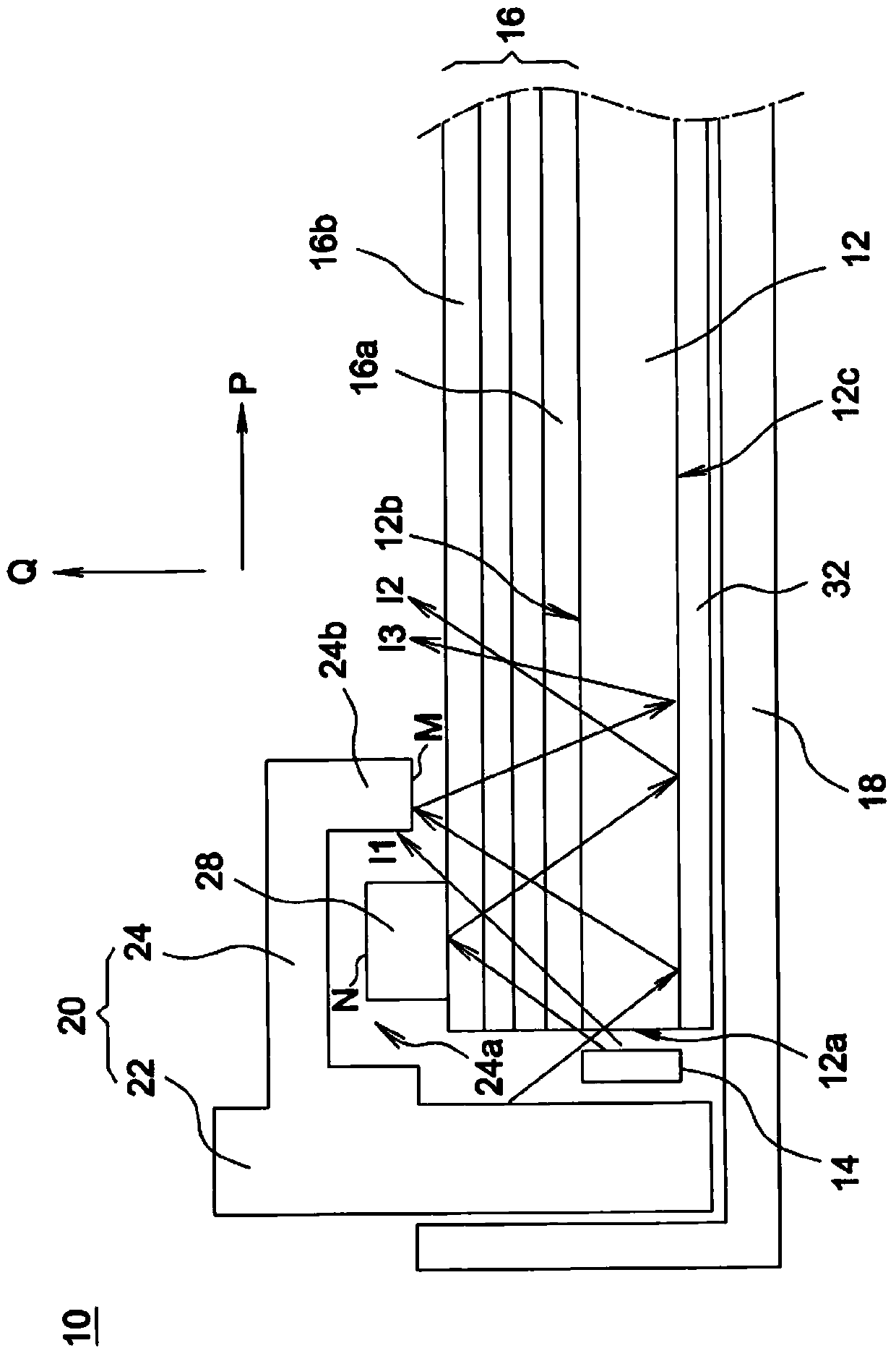
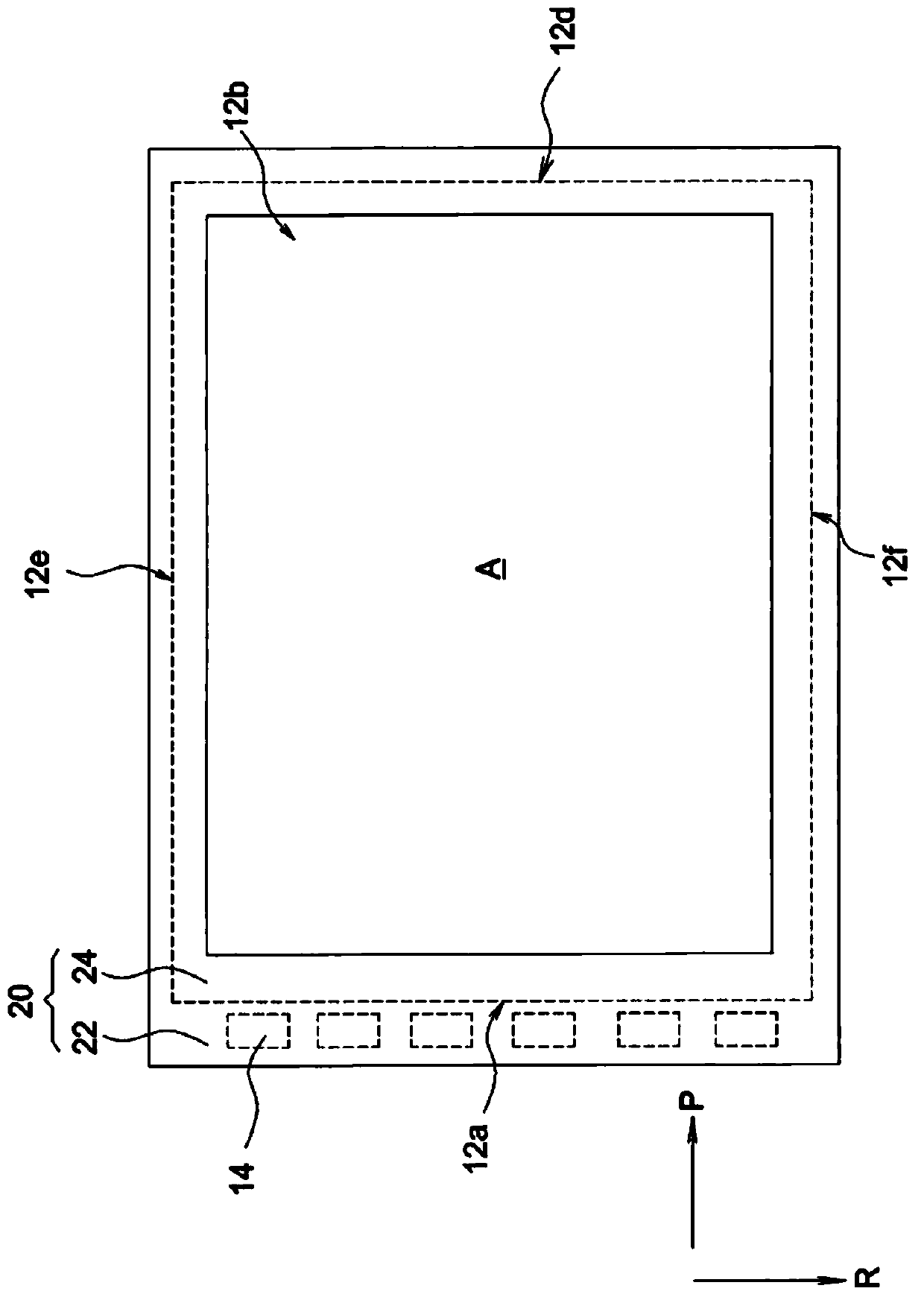
[0028] Figure 2A It is a schematic partial cross-sectional view of a backlight module according to an embodiment of the present invention. Figure 2B for Figure 2A The schematic diagram of the top view of the backlight module, and Figure 2B to omit Figure 2A Some of the components are described below for convenience. Such as Figure 2A and 2B As shown, a backlight module 10 includes a light guide plate 12 , at least one light source 14 , an optical film set 16 , a back plate 18 , a pl...


PUM


Abstract

A backlight module comprises a light guide plate, at least one light source, an optical diaphragm group, a back board, a rubber frame and a structure. The light guide plate is provided with at least one light incident face, a light emergent face and a bottom face. Each light source is arranged on the corresponding light incident face and used for emitting a beam of blue light. The optical diaphragm group is arranged on the light emergent face of the light guide plate in a stacked manner and comprises a color conversion sheet converting blue light into white light. The rubber frame is provided with a body portion and an extension portion, wherein the body portion abuts against the back board, and the extension portion extends from the body portion to the position above the optical diaphragm group. The side, facing the light guide plate, of the extension portion is provided with a groove and a protrusion structure, wherein the groove is recessed in the direction opposite to the light guide plate, the protrusion structure protrudes towards the light guide plate, and the distance between the protrusion structure and the body portion is larger than that between the groove and the body portion. The structure is arranged on the optical diaphragm group and contained in the groove, and an interval exists between the structure and the wall surfaces of the groove. The backlight module can improve the color conversion efficiency, reduce light leak and relieve the edge bluing problem.

Description

technical field [0001] The invention relates to a backlight module. Background technique [0002] figure 1 It is a partial cross-sectional schematic diagram of a conventional backlight module. Such as figure 1 As shown, the plastic frame 102 of the backlight module 100 is limited on the backplane 104 by means of alignment and abutment. Because the backlight module 100 has an edge with a narrow frame, the light I reflected by the plastic frame 102 easily leaks out from the gap between the plastic frame 102 and the optical film set 108 above the light guide plate 106 . If the light I is emitted by the blue light source 114, it is easy to form blue light leakage or blue halo, which will cause the problem of bluish border and affect the quality of the picture. [0003] The paragraph "Background Technology" is only used to help understand the content of the present invention, so the content disclosed in the "Background Technology" paragraph may contain some prior art that is ...

Claims


Application Information

Patent Timeline
Patent Type & Authority Patents(China)
IPC IPC(8): F21S8/00F21V13/00F21Y115/10
Inventor 陈慧娟曾贵鸿陈建翔
Owner CORETRONIC
Why Eureka
Try Eureka