
Flame detecting system

一种火焰检测、检测光的技术,应用在感测来自气体/火焰的辐射、测量装置、光度测定法等方向,能够解决难以迅速地检测火焰有无、花费积分时间等问题

Active Publication Date: 2016-12-07
YAMATAKE HONEYWELL CO LTD
View PDF12 Cites 6 Cited by
  • Summary
  • Abstract
  • Description
  • Claims
  • Application Information

AI Technical Summary

Problems solved by technology

However, with this method, since the current flowing between the electrodes needs to be integrated, and the integration time is taken even when the flame is eliminated, it takes time until the flame is detected. As a result, it is difficult to quickly detect the presence or absence of the flame.

Method used


Image

  • Flame detecting system
  • Flame detecting system
  • Flame detecting system

Examples


Embodiment 1

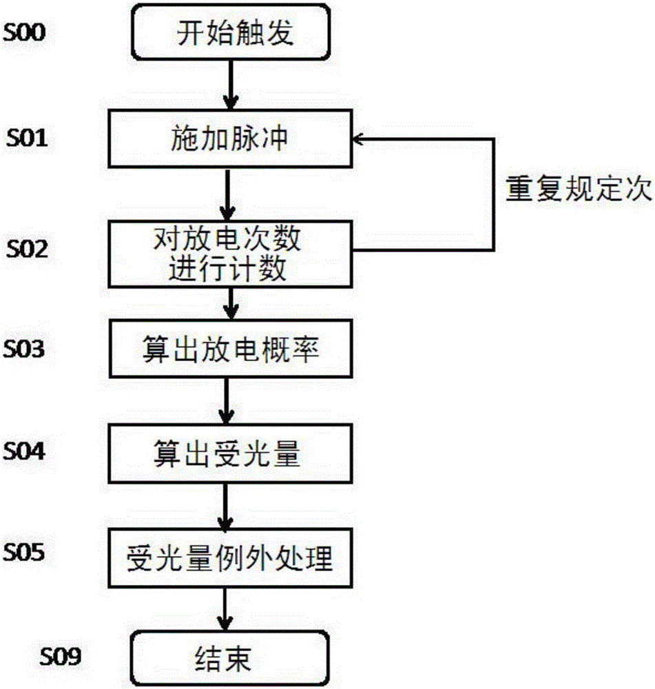
[0074] according to image 3 The process is described (refer to the steps in the figure as Snn).

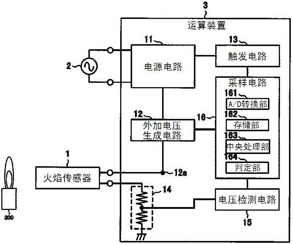
[0075] The central processing unit 163 plays a role in driving the flame sensor 1 with a pulse voltage, and calculating the amount of light received by the flame based on the driving result of the flame sensor 1.

[0076] • Start after receiving a predetermined trigger (S00).

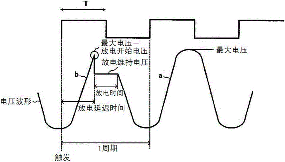
[0077] The driving of the flame sensor is to operate the applied voltage generating circuit 12 to apply a voltage equal to or higher than the discharge start voltage to the flame sensor 1 with a rectangular pulse T of a certain pulse width (S01).

[0078] The signal obtained by the voltage detection circuit 15 is used to count the number of times the flame sensor 1 is discharged by applying the pulse T to the flame sensor 1 a certain number of times (S02).

[0079] · Calculate the discharge probability P based on the number of discharges and the number of applied pulses (S03).

[0080] · Calculate the amount of recei...

Embodiment 2

[0090] Under the condition A in the above equation 8, the pulse width T and the discharge probability P are known. Under a certain amount of light, the flame sensor 1 is activated multiple times with the pulse width T, and the discharge probability is P. At this time, when the next pulse is applied (set it as condition C), I want to adjust the discharge probability to an arbitrary value P c . In this case, the relationship between Condition A and Condition C is as shown in Equation 11. However, it is assumed that the received light quantity Q does not change. Formula 12 is obtained by deforming it.

[0091] 【Number 11】

[0092] Q B T C Q A T A = log ( 1 - P A ) ( 1 - P C )

[0093] 【Number 12】

[0094] T c = T A log ( 1 - P A ) ( 1 - P C )

[0095] According to Equation 12, the pulse width Tc that should be set under the condition C can be obtained. Able to...


PUM


Abstract

To easily obtain a quantity of received light with computation by only measuring pulses of an electric signal related to a flame sensor, a flame detecting system is disclosed comprising: a flame sensor to detect light and a calculating device, in which the calculating device includes an applied voltage generating portion configured to generate a pulse to drive the flame sensor, a voltage detecting portion configured to measure an electric signal flowing in the flame sensor, a storing portion configured to store sensitivity parameters of the flame sensor in advance, and a central processing unit configured to obtain a quantity of received light of a flame using parameters of a known quantity of received light, a pulse width, and a discharge probability of the sensitivity parameters, and a discharge probability obtained from an actual pulse width and the measured number of discharge times.

Description

Technical field [0001] The invention relates to a flame detection device for detecting the presence or absence of flame. Background technique [0002] Conventionally, there are known electron tubes for detecting the presence or absence of a flame based on ultraviolet rays emitted from the flame in a combustion furnace or the like. The electron tube includes: an airtight container filled with a predetermined gas; an electrode support pin that penetrates the airtight container; and two electrodes supported by the electrode support pin in parallel in the airtight container. In this kind of electron tube, when a predetermined voltage is applied between the electrodes via the electrode support pin, when ultraviolet rays are irradiated to an electrode arranged opposite to the flame, electrons are released from the electrode due to the photoelectric effect. These electrons It is continuously excited to form an electron avalanche between the electrode and the other electrode. Therefore...

Claims


Application Information

Patent Timeline
Patent Type & Authority Applications(China)
IPC IPC(8): F23M11/04
CPCF23M11/04G01J5/0018G01J2001/444G01J1/429G01J1/4204G01J5/064F23M11/045F23N5/08G01J1/16G01J1/18G01J2001/1621H01J19/82
Inventor 森雷太
Owner YAMATAKE HONEYWELL CO LTD
Learn More