
Furnace top CO detection device and method of ignition furnace

A detection device and ignition furnace technology, applied in the field of ignition furnace top CO detection device, dynamic patrol type ignition furnace top CO detection device, can solve the problems of inability to determine the location of gas leakage points, small monitoring range, etc., and reduce maintenance. range, reduce labor intensity, and improve the effect of safety factor

Active Publication Date: 2016-12-07
ZHONGYE-CHANGTIAN INT ENG CO LTD
View PDF10 Cites 11 Cited by
  • Summary
  • Abstract
  • Description
  • Claims
  • Application Information

AI Technical Summary

Problems solved by technology

[0009] The object of the present invention is to provide a dynamic patrol type ignition furnace top CO detection device and detection method to solve the problems of the existing ignition furnace top CO detection device with a small monitoring range and the inability to judge the position of the gas leakage point

Method used


Image

  • Furnace top CO detection device and method of ignition furnace
  • Furnace top CO detection device and method of ignition furnace
  • Furnace top CO detection device and method of ignition furnace

Examples


Embodiment 1

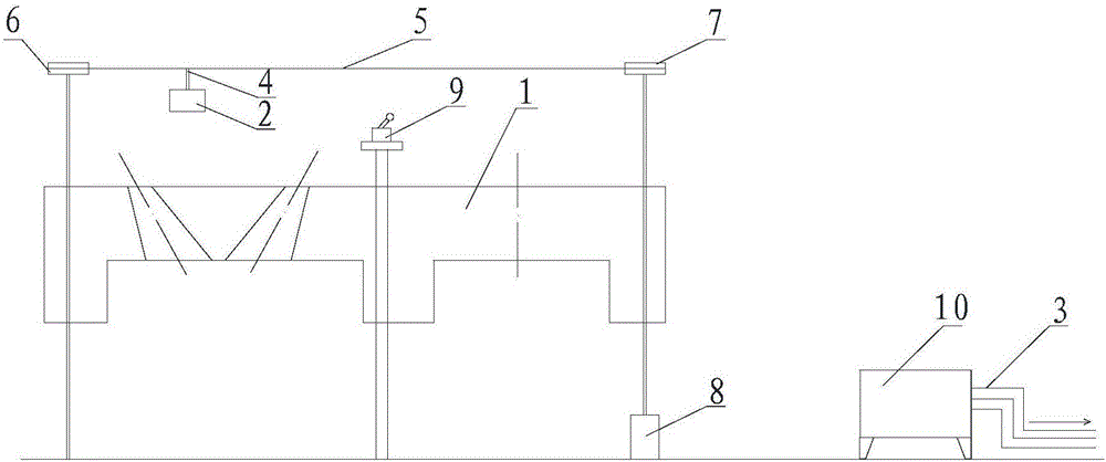
[0045] For the CO detection device on the ignition furnace top of the present embodiment one, please refer to image 3 , the closed circuit is located above the top 1 of the ignition furnace. The CO detector 2 is installed below the closed circuit, and the closed circuit drives the CO detector to circulate on the top 1 of the ignition furnace. Obviously, since the CO detector 2 moves along with the closed circuit, the CO detector 2 is a CO wireless detector, and the cables and cable bushings can be omitted, which not only saves space on the furnace top, but also reduces the possibility of operating problems. Hazard of tripping over cable glands and falling.

[0046] When the CO wireless detector is hung under the closed circuit, the CO wireless detector is closer to the top 1 of the ignition furnace, so that the CO concentration at each position on the top 1 of the ignition furnace can be accurately monitored. Among them, preferably but not necessarily image 3 As shown in ...

Embodiment 2

[0058] The difference from Embodiment 1 is that the closed route in Embodiment 2 is rhombus-shaped, so that the closed route drives the CO wireless detector to circulate along the diamond-shaped loop. Please refer to Figure 5 .

[0059] On this basis, the number of driving sprockets 7 in the second embodiment is one, and the number of driven sprockets 6 is three, and they are distributed at the four vertices of the rhombus.

[0060] In the above embodiments, the locator can be in the form of a limit switch 9 . Specifically, when the CO wireless detector passes the set position, the limit switch 9 is turned on, and the limit switch 9 sends a trigger signal to the controller, and the controller receives the trigger signal The timing of the signal and the speed at which the closed line moves calculate the real-time position of the CO wireless detector.

[0061] see further Figure 5 , when the CO detector 2 passes above the limit switch 9, the CO detector 2 presses the limit ...


PUM


Abstract

The invention relates to the technical field of ignition furnaces and provides a furnace top CO detection device and method of an ignition furnace. A closed line of the furnace top CO detection device of the ignition furnace is distributed above a furnace top of the ignition furnace; a CO wireless detector is mounted on the closed line and moves along with the closed line, and is used for transmitting a detected CO concentration value to a controller; a positioner is used for tracking the position of the CO wireless detector and transmitting position information to the controller; a mapping relation between the CO concentration value and the position information is established by the controller. The CO wireless detector provided by the scheme does circulating movement at the furnace top of the ignition furnace and a monitoring range can cover the whole furnace top of the ignition furnace; gas leakage of any valve at the furnace top of the ignition furnace is captured by the CO detector, so that the safety coefficient of production is greatly improved. Furthermore, the scheme can analyze a position range of a gas leakage point according to the CO concentration value at each position, so that an overhauling range of an operator can be greatly reduced; the time can be saved and the working efficiency can also be improved; the labor intensity can be alleviated.

Description

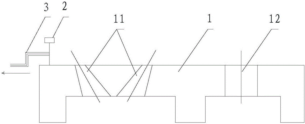
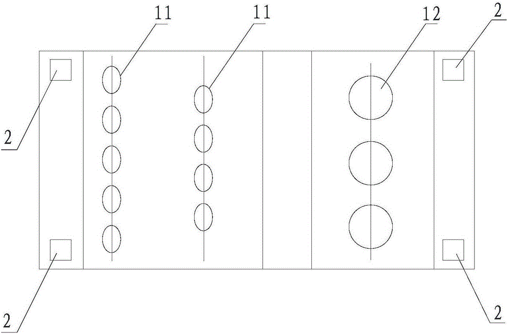
technical field [0001] The invention relates to the technical field of ignition furnaces, in particular to an ignition furnace top CO detection device and detection method, more specifically a dynamic patrol type ignition furnace top CO detection device and detection method. Background technique [0002] In the modern sintering process, the ignition furnace is used to provide a high-temperature ribbon flame to the surface of the mixture, so that the solid fuel in it is ignited and burned, and the surface mixture is sintered under the heat release of the high-temperature flue gas of the ignition furnace and the solid fuel combustion. At the same time, sufficient oxygen is provided by the exhaust fan to transfer the heat accumulated in the surface layer to the next layer of mixture, so that the solid fuel in the next layer continues to burn, so that the sintering process proceeds rapidly downwards and completes the sintering process. [0003] See figure 1 with figure 2 The ...

Claims


Application Information

Patent Timeline
Patent Type & Authority Applications(China)
IPC IPC(8): G01N33/00G08C17/02
CPCG01N33/004G08C17/02
Inventor 周浩宇
Owner ZHONGYE-CHANGTIAN INT ENG CO LTD
Learn More