Detection system and method for broken needle in workpiece
A detection system and detection method technology, which is applied in the field of needle detection machines, can solve problems such as inability to detect metal workpieces, achieve the effect of improving detection accuracy and avoiding detection interference
- Summary
- Abstract
- Description
- Claims
- Application Information
AI Technical Summary
Problems solved by technology
Method used
Image
Examples
Embodiment 1
[0040] This embodiment provides a needle detector, which can better detect broken needles in workpieces, especially detect broken needles made of strong magnetic materials in workpieces made of weak magnetic materials, and can be better suitable for such as Detect broken needles in aluminum alloy castings such as mobile phone backplanes.
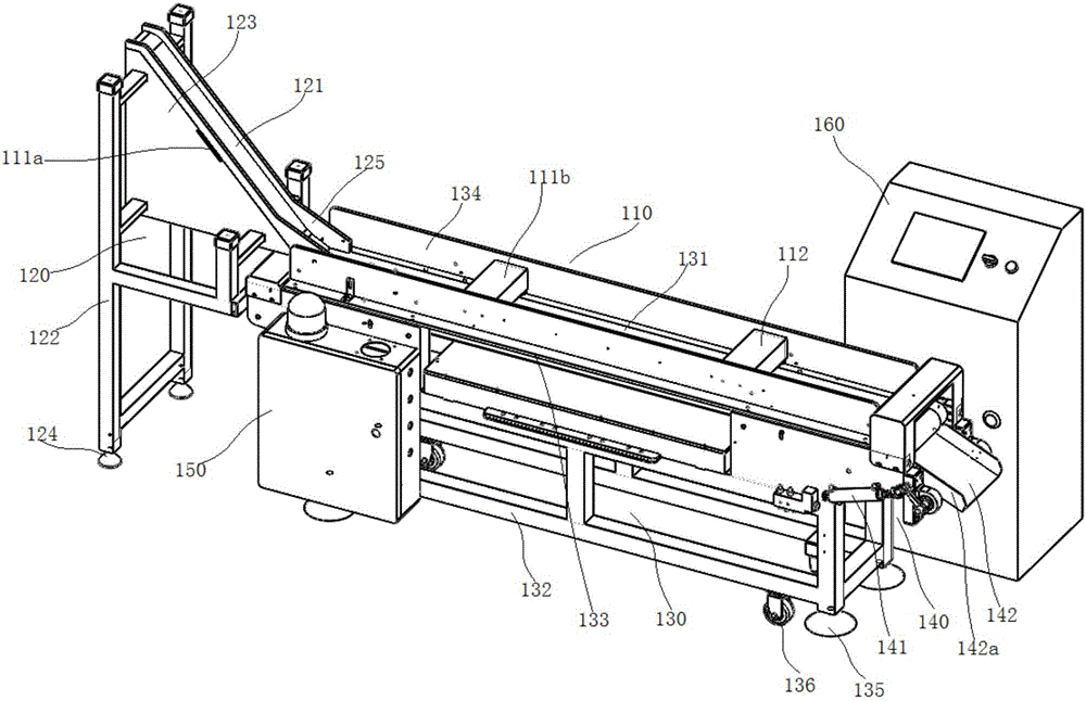
[0041] Such as figure 1 As shown, it includes a needle detector body 110. The needle detector body 110 includes a conveying unit for conveying workpieces to be inspected. The conveying unit is provided with at least one detection unit. module and magnetic detection module.
[0042] The detection unit of the needle detector in this embodiment is equipped with a magnetization module and a magnetization detection module that are independent of each other; this enables the workpiece to be firstly magnetized by the magnetization module when it is running at the conveying unit, because the workpiece is a weak magnetic material Therefore, the att...
Embodiment 2
[0057] This embodiment also provides a needle detector, which differs from Embodiment 1 in that: In this embodiment, in order to overcome the magnetic anisotropy, another setting method of the magnetizing module is provided; wherein, any Each detection unit includes a plurality of magnetization modules, and the plurality of magnetization modules are respectively used to magnetize the workpiece to be inspected in different directions.
[0058] In this embodiment, the relationship between the number and spatial position of multiple magnetization modules arranged at any detection unit should conform to the analysis conclusion in Embodiment 1, that is, the blind zone of magnetization needs to be covered.
Embodiment 3
[0060] On the basis of Embodiment 1 or 2, this embodiment provides a split rack structure.
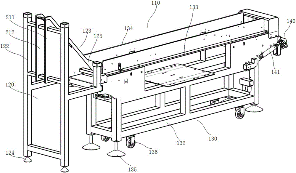
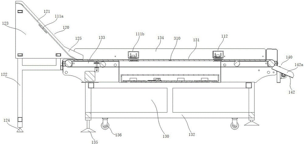
[0061] see figure 1 , 2 Or 3, the split frame structure in the present embodiment comprises mutually independent feeding frame 120 and conveying frame 130, and feeding frame 120 place is provided with feed channel 121, and conveying frame 130 place is provided with conveying path 131 ; the feeding channel 121 forms a drop in the height direction, the conveying channel 131 is arranged horizontally, and the lower end of the feeding channel 121 is gradually flush with the transmitting channel 131 and extends above the transmitting channel 131 .
[0062] Such as Figure 4 As shown, the feed frame 120 includes a first support member 122 and a first track member 123, and the first track member 123 includes a first connecting plate 211 and a second connecting plate 212 arranged parallel to each other, and the first connecting plate 211 and the second connecting plate 211 A feeding track pl...
PUM
 Abstract
Description
Claims
Application Information
 - R&D
- Intellectual Property
- Life Sciences
- Materials
- Tech Scout
- Unparalleled Data Quality
- Higher Quality Content
- 60% Fewer Hallucinations
Browse by: Latest US Patents, China's latest patents, Technical Efficacy Thesaurus, Application Domain, Technology Topic, Popular Technical Reports.
© 2025 PatSnap. All rights reserved.Legal|Privacy policy|Modern Slavery Act Transparency Statement|Sitemap|About US| Contact US: help@patsnap.com


