Field diaphragm and pyrometer optical sighting device

A field diaphragm and diaphragm hole technology, applied in the field of field diaphragm, can solve the problems of not ensuring optical conjugation and affecting the normal use of optical instruments, etc.

Inactive Publication Date: 2016-12-07
NAT INST OF METROLOGY CHINA
View PDF4 Cites 2 Cited by
  • Summary
  • Abstract
  • Description
  • Claims
  • Application Information

AI Technical Summary

Problems solved by technology

The position of the discrete reticle is different from that of the field diaphragm, so the optical path from the discrete reticle to the eyepiece is different from the optical path from the field diaphragm to the eyepiece. During the use of the optical aiming system of an optical instrument, the discrete reticle and The relative position of the field diaphragm may change, causing the position of the discrete reticle to move in the field of view. Especially in long-term use, the position of the discrete reticle will change greatly, making the separation between the discrete reticle and the field diaphragm Optical conjugation cannot be ensured, thus affecting the normal use of optical instruments

Method used


Image

  • Field diaphragm and pyrometer optical sighting device
  • Field diaphragm and pyrometer optical sighting device
  • Field diaphragm and pyrometer optical sighting device

Examples


Embodiment Construction

[0018] In order to make the object, technical solution and advantages of the present invention clearer, the present invention will be further described in detail below in combination with specific embodiments and with reference to the accompanying drawings. It should be understood that these descriptions are exemplary only, and are not intended to limit the scope of the present invention. Also, in the following description, descriptions of well-known structures and techniques are omitted to avoid unnecessarily obscuring the concept of the present invention.

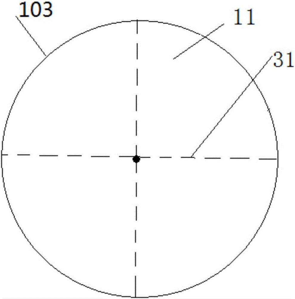
[0019] figure 1 is a reticle diagram of the field diaphragm according to the first embodiment of the present invention.

[0020] Such as figure 1 As shown, the front side of the field diaphragm 103 in the embodiment of the present invention is a reflective mirror 11 , and the rest is covered with a black coating. The front surface of the main body of the field diaphragm 103 is provided with a dividing line 31 .

[002...


PUM


Abstract

The embodiment of the invention discloses a field diaphragm. The obverse side of the field diaphragm is a reflecting mirror face, the other part is covered with a black coating, and division lines are arranged on the obverse side of a field diaphragm body. According to the field diaphragm, the division lines and the field diaphragm are located on the same plane, the relative positions of the division lines and the field diaphragm are invariable, and therefore the problem that in the prior art, the imaging effect is influenced due to the fact that the relative positions of the field diaphragm and the division lines change is avoided. The invention further discloses a pyrometer optical sighting device including the field diaphragm. When the device is used, the relation positions of the division lines and the field diaphragm do not need to be installed and adjusted, and more precise sighting of the pyrometer optical sighting device is guaranteed.

Description

technical field [0001] The invention relates to an optical aiming device of a pyrometer, in particular to a field diaphragm. Background technique [0002] In the optical aiming system of the pyrometer, it is necessary to use the reticle to mark the relative position of the target imaging. Usually, a discrete reticle with a reticle is installed in the optical path of the aiming system. This scheme requires design, installation and commissioning And other technical means to realize the optical conjugation of the reticle and the field diaphragm. Existing discrete reticles are usually installed in or before the eyepiece assembly of the aiming system. The position of the discrete reticle is different from that of the field diaphragm, so the optical path from the discrete reticle to the eyepiece is different from the optical path from the field diaphragm to the eyepiece. During the use of the optical aiming system of an optical instrument, the discrete reticle and The relative p...

Claims


Application Information

Patent Timeline
Patent Type & Authority Applications(China)
IPC IPC(8): G02B5/00G02B23/00
CPCG02B5/005G02B23/00
Inventor 王景辉原遵东王铁军卢小丰
Owner NAT INST OF METROLOGY CHINA
Why Eureka
Try Eureka