Device for ultrasonic ranging and ranging method thereof

A technology of ultrasonic waves and ultrasonic probes, applied in the direction of measuring devices, sound wave re-radiation, radio wave measuring systems, etc., can solve the problems of reducing the test accuracy of ultrasonic ranging devices and increasing ranging errors, so as to improve the service life and use Safe and convenient, scientific and reasonable structure

Inactive Publication Date: 2020-07-24
陈启明
View PDF0 Cites 2 Cited by
  • Summary
  • Abstract
  • Description
  • Claims
  • Application Information

AI Technical Summary

Problems solved by technology

[0004] The present invention provides a device for ultrasonic distance measurement and its distance measurement method, which can effectively solve the problem that the structure of the ultrasonic distance measurement device proposed in the above background technology is simple, and the core component of the ultrasonic distance measurement device, the ultrasonic probe, is in use and idle. Both are exposed to the air, resulting in the phenomenon that the distance measurement error increases due to the collision and dust pollution of the ultrasonic probe after long-term use, thereby reducing the testing accuracy of the ultrasonic distance measuring device.

Method used


Image

  • Device for ultrasonic ranging and ranging method thereof
  • Device for ultrasonic ranging and ranging method thereof
  • Device for ultrasonic ranging and ranging method thereof

Examples


Embodiment

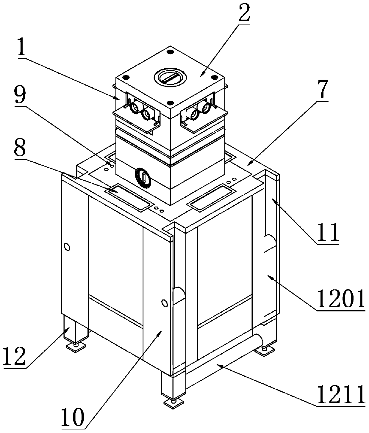
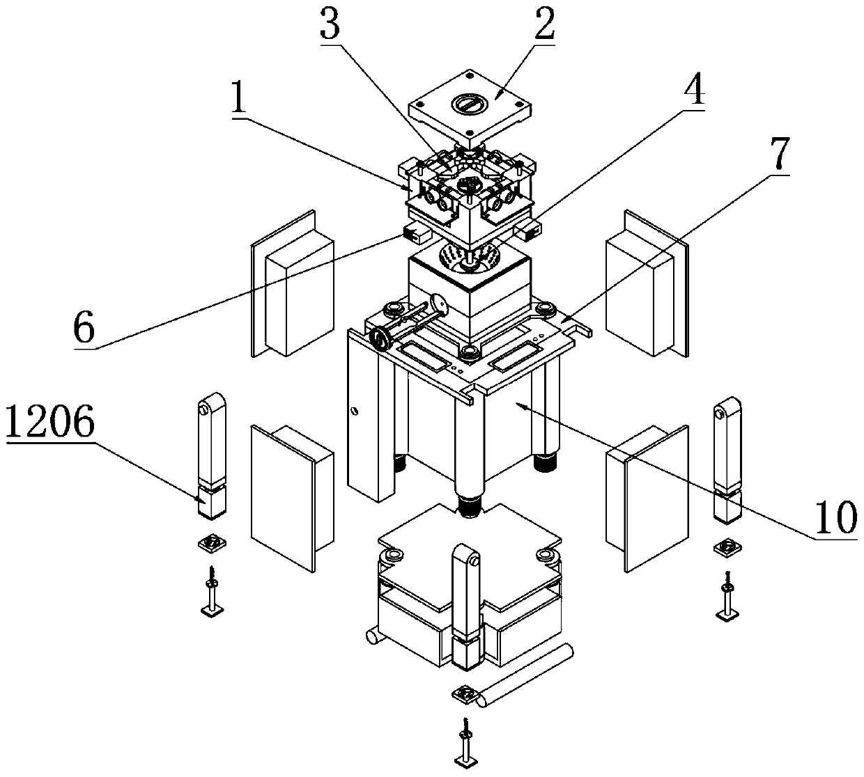
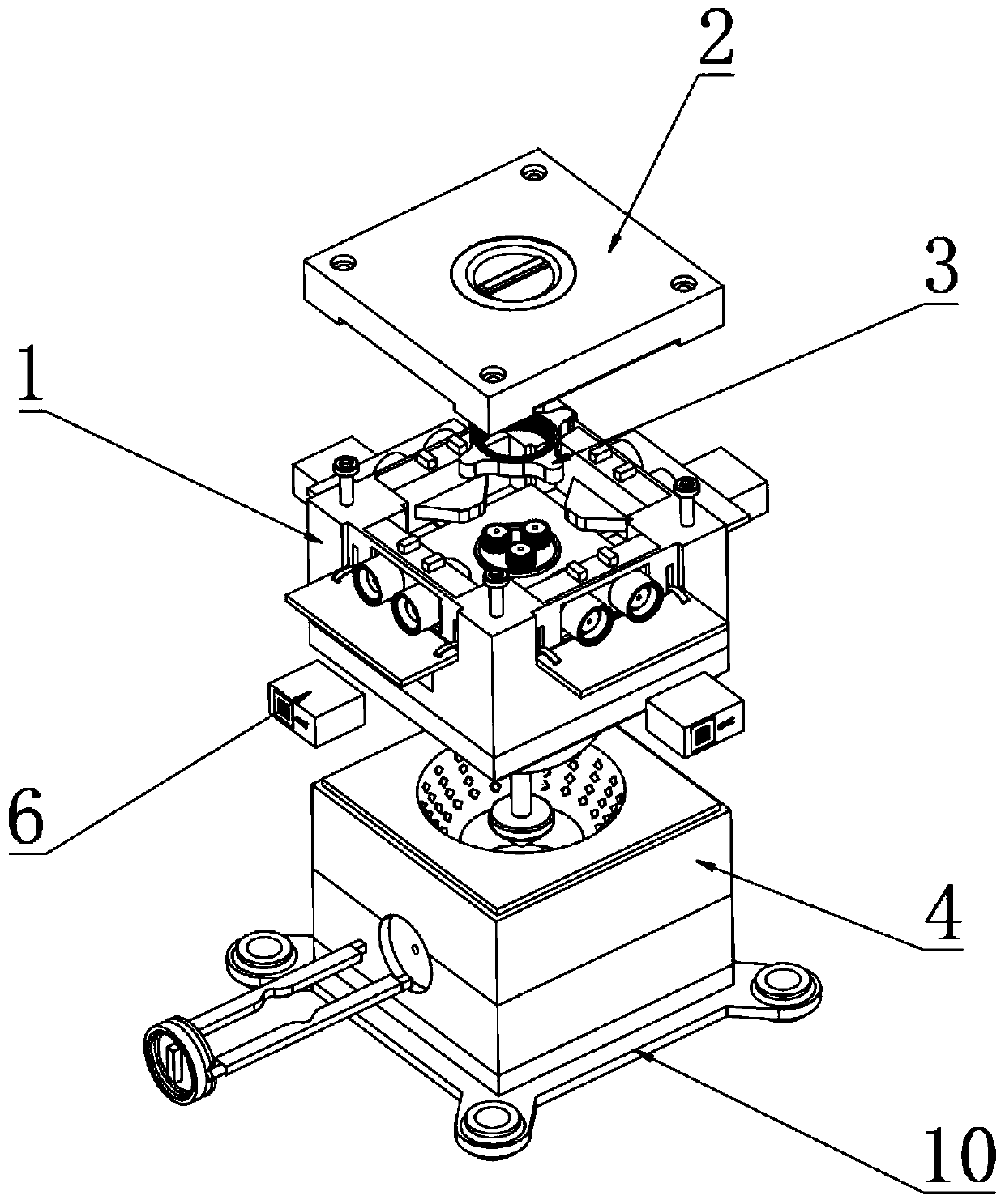
[0066] Example: such as Figure 1-10 As shown, the present invention provides a technical solution, a device for ultrasonic distance measurement, including an upper installation box 1, the top of the upper installation box 1 is fixedly connected with a fixed cover 2 through an inner hexagonal bolt, and the upper installation box 1 is internally provided with Protective ejection mechanism 3;

[0067] The protective ejection mechanism 3 includes an installation side cavity 301, a guide chute 302, a storage spring 303, a small driving plate 304, an ultrasonic probe 305, an ejection triangular plate 306, a limit frame 307, an ejection rotating plate 308, a transmission gear 309, Driving gear 310, driving motor 311, sealing rotating plate 312, receiving vertical groove 313 and return spring piece 314;

[0068] The four sides inside the upper installation box 1 are provided with an installation side chamber 301, and the bottom end of the inner side of the installation side chamber ...


PUM


Abstract

The invention discloses a device for ultrasonic ranging. The device comprises an upper mounting box, the top end of the upper mounting box is fixedly connected with a fixed cover through a hexagon socket screw, mounting side cavities are formed in the four side faces of the interior of the upper mounting box correspondingly, guide sliding grooves are symmetrically formed in the bottom ends of theinner sides of the mounting side cavities, a storage spring is fixedly connected to one end of the inner side of each guide sliding groove, a small driving square plate is fixedly connected to the position, corresponding to the inner side of the corresponding guide sliding groove, of one end of each storage spring, an ultrasonic probe is mounted at the top end of each small driving square plate, and an ejection triangular plate is adhered to the middle part of one end of each ultrasonic probe. By means of the device, a sealed rotating plate is driven to turn over in the box through a reset spring piece, and the sealed rotating plate seals the tail ends of the ultrasonic probes, so that collision of the ultrasonic probes and attachment of external dust to the ultrasonic probes are effectively avoided, reduction of measurement accuracy of the ultrasonic probes due to collision and dust attachment is prevented, and detection accuracy of the ultrasonic probes after long-term use is improved.

Description

technical field [0001] The invention relates to the technical field of ultrasonic ranging, in particular to an ultrasonic ranging device and a ranging method thereof. Background technique [0002] Ultrasonic refers to sound waves with a vibration frequency higher than 20kHz. It has the characteristics of high vibration frequency, good directionality, and strong penetrating ability. It is widely used in distance measurement, speed measurement, welding, gravel, cleaning, sterilization, etc. Ultrasonic can It can effectively propagate in many media such as gas, liquid, solid, solid solution, etc., and is not affected by other factors such as light, dust, electromagnetic, moisture, etc., and the propagation speed in the same propagation medium remains basically unchanged. This non-contact detection technology can be completed in a relatively harsh environment, and can be widely applied to the measurement of vehicle reversing, building construction and industrial site liquid leve...

Claims


Application Information

Patent Timeline
Patent Type & Authority Applications(China)
IPC IPC(8): G01S7/521G01S15/08
CPCG01S7/521G01S15/08
Inventor 陈启明
Owner 陈启明
Why Eureka
Try Eureka