Cylindrical cable net reflection system driven by three telescoping rods

A technology of reflection system and telescopic rod, which is applied in the direction of control/regulation system, non-electric variable control, control without feedback, etc., can solve the disadvantages of large-scale promotion and use, high construction cost and material cost, and cannot be used directly Problems such as on the ground, to achieve the effect of low development cost and maintenance cost, less floor space, and shorten the development cycle

Active Publication Date: 2016-12-07
XIDIAN UNIV
View PDF6 Cites 5 Cited by
  • Summary
  • Abstract
  • Description
  • Claims
  • Application Information

AI Technical Summary

Problems solved by technology

The 500m-aperture spherical radio telescope to be built in my country in 2016 has adopted system-level innovative design ideas based on active reflector technology and flexible cable traction feed source technology, and its aperture surface density is still 6.6Kg / m 2 , not only high construction cost and material cost, but also unfavorable for wide-scale popularization and use
[0003] In space, large-scale deployable antennas with cable-net structures have been widely used. Since the gravity of the space environment is close to zero, this soft structure combined with rigidity and flexibility can form the desired surface accuracy and is ultra-light in weight. Density not exceeding 0.4Kg / m 2 , but this kind of cable net structure under the action of no gravity cannot be directly used on the ground

Method used


Image

  • Cylindrical cable net reflection system driven by three telescoping rods
  • Cylindrical cable net reflection system driven by three telescoping rods
  • Cylindrical cable net reflection system driven by three telescoping rods

Examples


Embodiment 1

[0043] Embodiment 1: A ring-column type cable-net reflection system with a diameter of 5 m.

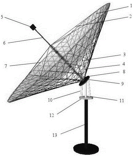
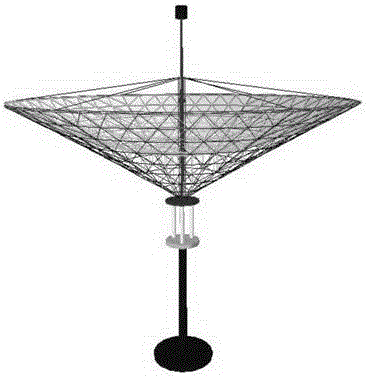
[0044] refer to figure 1 and figure 2 , the present invention includes reflection device and attitude control device:

[0045]The reflection device includes a mesh surface cable 1, an upper and lower support cable 2, an adjustment cable 3, a fastening cable 4, a feed source or a heat collector 5, a central pillar 6 and an expandable outer ring unit 7;

[0046] refer to image 3 , the expandable outer ring unit 7 includes a plurality of radially drilled hollow tubes 71 and a plurality of connecting joints 74, and every two hollow tubes are connected to each other through a connecting joint to form a self-folding hollow circle Ring; the aperture of outer ring unit 7 can be changed by changing the quantity and the length of hollow circular tube 71, i.e. the design aperture of reflector, and the quantity of hollow circular tube 71 gets forty-eight among the present example, makes the ...

Embodiment 2

[0060] Embodiment 2: A ring-column type cable net reflection system with a diameter of 15m.

[0061] The structural form of the reflection system of this example is the same as that of Embodiment 1, but the structural parameters are changed: the diameter of the reflection device of this embodiment is 15m, and the number of the upper and lower support cables 2 is twelve.

[0062] The staggered symmetrical connection of the above-mentioned center pillar 6 and the rope between the upper pin 72 and the lower pin 73 respectively adopts the second connection form, that is, the connection holes at the upper and lower ends of the center pillar 6 are connected with the pins of the upper pin 72 and the lower pin 73 respectively. The holes are connected symmetrically by front and rear twelve support cables.

[0063] refer to Figure 8 , between the upper end connection hole of the central pillar 6 and the pin hole of the upper pin 72, the front 12 support cables are symmetrically connec...


PUM


Abstract

The invention discloses a cylindrical cable net reflection system driven by three telescoping rods, aiming to solve the problems that a reflection system in the prior art is large in intensity and complex in structure. The cylindrical cable net reflection system includes a net surface cable (1), a fastening cable (4), a center column (6), an expandable outer circular ring unit (7), an upper platform (8), the three telescoping rods (10), a lower platform (12), and a support platform (13), a feed source (5) is arranged at the top of the center column, the center column and the outer circular ring are connected through upper and lower support cables (2), an adjusting cable (3) is connected between the net surface cable and the fastening cable to control the deformation of the reflection plane by changing the length, the upper ends of the three telescoping rods are connected with the upper platform through a spherical hinge connection structure (9), the lower end is connected with the lower platform through a revolute pair connection structure (11), and by changing the length of the three telescoping rods, the attitude control of the reflection device is realized. The reflection system is simple in structure, portable and flexible, accurate in attitude control, and can be used for the reflection or convergence of optical and electrical energies.

Description

technical field [0001] The invention belongs to the technical field of mechanical structures, in particular to a tracking and positioning ring-column type cable net reflection system, which can be used for reflection or convergence of electromagnetic energy or light energy. Background technique [0002] Large-scale reflector systems have not only been widely used in the field of electronic information technology, but also gradually expanded and applied in the field of solar energy application technology. A large reflector system generally includes a reflector, a support frame, and a control device for adjusting the pitch angle and azimuth angle. Among them, the surface accuracy of the reflecting surface is an important index to ensure the effective operation of the reflector. Due to the effect of gravity, wind and rain and other loads in the surface environment, in order to ensure the surface accuracy of the reflector, the reflector panels in the large reflector structure a...

Claims


Application Information

Patent Timeline
Patent Type & Authority Applications(China)
IPC IPC(8): G05D3/10
CPCG05D3/10G05D3/105
Inventor 郑飞陈梅芮喜
Owner XIDIAN UNIV
Why Eureka
Try Eureka