Image correction method and device

An image correction and image technology, which is applied in the field of image processing, can solve problems such as low correction efficiency, untimely display of images, and increased display time, so as to reduce costs and improve user experience

Active Publication Date: 2016-12-07
SHANGHAI UNITED IMAGING HEALTHCARE
View PDF3 Cites 11 Cited by
  • Summary
  • Abstract
  • Description
  • Claims
  • Application Information

AI Technical Summary

Problems solved by technology

For the first correction method, the corrected image quality is poor and does not meet the actual clinical needs
For the second correction method, since it is necessary to collect a dark field image after the image is collected, and then use the dark field image to correct the collected image, the correction efficiency is low and the quality of the corrected image is low.

Method used


Image

  • Image correction method and device
  • Image correction method and device
  • Image correction method and device

Examples


Embodiment Construction

[0049] In order to make the above objects, features and advantages of the present invention more comprehensible, specific implementations of the present invention will be described in detail below in conjunction with the accompanying drawings. In the following description, specific details are set forth in order to provide a thorough understanding of the present invention. However, the present invention can be implemented in many other ways than those described here, and those skilled in the art can make various changes without departing from the connotation of the present invention. Accordingly, the present invention is not limited to the specific embodiments disclosed below.

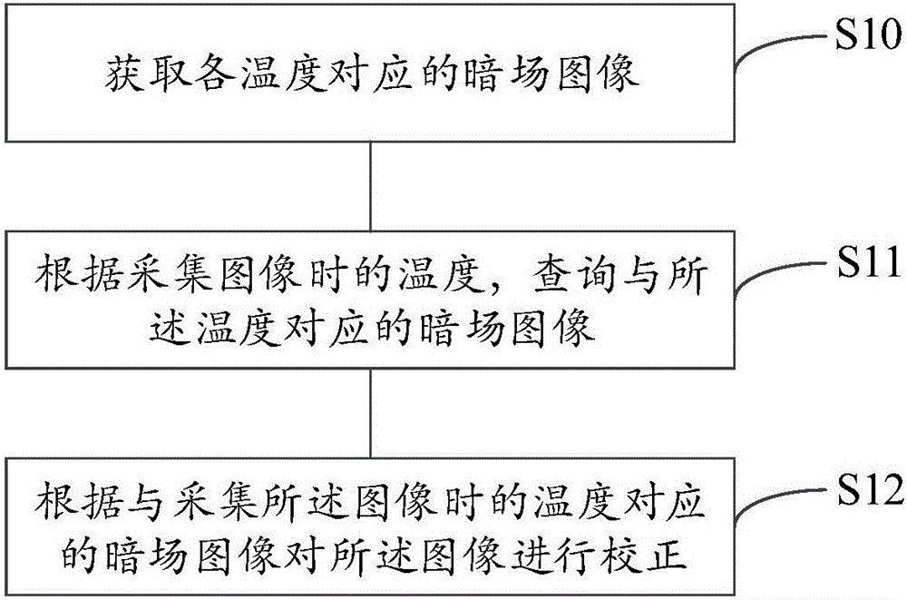
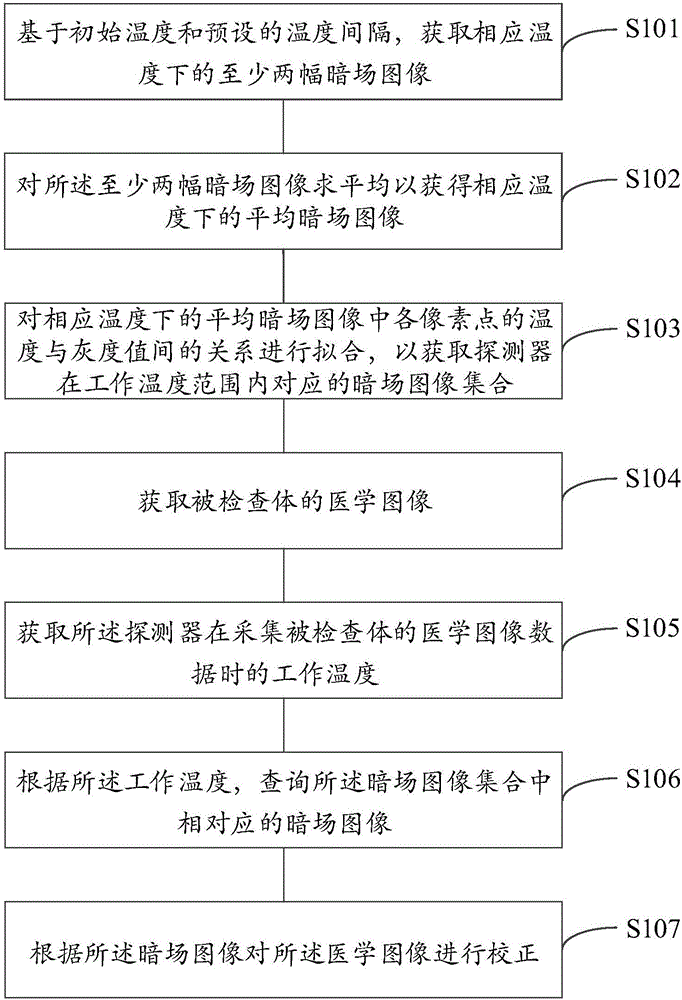
[0050] As described in the prior art, two methods are usually used to correct the image collected by the flat panel detector. The inventor knows through analysis that for the first method, it only collects dark field images at a specific temperature , and correct the image collected by the detector ba...


PUM


Abstract

The invention discloses an image correction method and device. The image correction method comprises the steps of obtaining a dark field image corresponding to each temperature; according to the temperature obtained during image collection, searching for the dark field image corresponding to the temperature; according to the dark field image corresponding to the temperature obtained during image collection, correcting the image. According to the image correction method, the correction speed is high, and the quality of the corrected image is high.

Description

technical field [0001] The invention relates to the technical field of image processing, in particular to an image correction method and device. Background technique [0002] In an X-ray photography system, the conversion of X-ray energy into an electrical signal is realized through a flat panel detector, so the performance of the flat panel detector has a great influence on the image quality of the X-ray photography system. Flat panel detectors can generally be divided into two types: amorphous selenium flat panel detectors and amorphous silicon flat panel detectors. The former belongs to direct conversion flat panel detectors, and the latter belongs to indirect conversion flat panel detectors. Due to the complex structure of the flat panel detector and the limitations of the manufacturing process, the original image output by the flat panel detector will have many defects, which directly affect the quality of the final image. Therefore, it is necessary to correct the image...

Claims


Application Information

Patent Timeline
IPC IPC(8): G06T5/00G06T11/00
CPCG06T5/005G06T11/008G06T2207/10081G06T2207/10116G06T2211/40
Inventor 崔凯牛杰冯娟胡扬
Owner SHANGHAI UNITED IMAGING HEALTHCARE
Why Eureka
Try Eureka