Drop type arrester

A surge arrester and drop-type technology, which is applied in the direction of resistors, resistor components, and other resistor networks, can solve the problems affecting the nonlinear volt-ampere characteristics of the main body of the zinc oxide arrester and the lightning protection effect of the main body of the zinc oxide arrester, and achieve Good lightning protection effect, easy to popularize and apply, safe and reliable to use

Inactive Publication Date: 2016-12-07
常德威迪电气有限责任公司
View PDF7 Cites 2 Cited by
  • Summary
  • Abstract
  • Description
  • Claims
  • Application Information

AI Technical Summary

Problems solved by technology

The dropper of the existing drop-out arrester is connected to the main body of the zinc oxide arrester through a tube clip, and the tube clip is directly sleeved in the varistor distribution area of ​​the main body of the zinc oxide arrester, so that the tube clip has to continuously compress the zinc oxide arrester in the clamped state. The varistor of the main body of the arrester applies pressure, which will affect the nonlinear volt-ampere characteristics of the main body of the zinc oxide arrester over time, and then affect the lightning protection effect of the main body of the zinc oxide arrester

Method used


Image

  • Drop type arrester
  • Drop type arrester
  • Drop type arrester

Examples


Embodiment 1

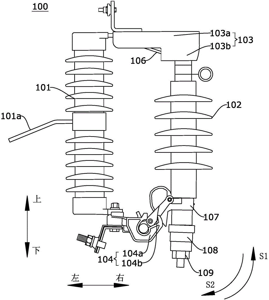
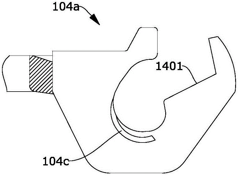
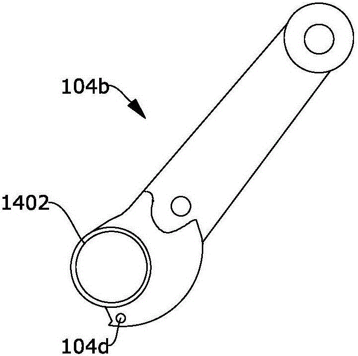
[0028] figure 1 It is a schematic structural diagram of the drop arrester 100 according to Embodiment 1 of the present invention; figure 2 It is a partial cross-sectional view of the first conductive seat of the drop-out arrester according to Embodiment 1 of the present invention; image 3 It is a schematic structural diagram of the second conductive seat of the dropout arrester according to Embodiment 1 of the present invention. Such as figure 1 and image 3 As shown, the drop arrester 100 includes an insulator 101 . The insulator 101 is preferably a ceramic insulator or a synthetic insulator. The insulator 101 can be installed on the utility pole or other positions to be installed through the holed sheet 101a in the middle.

[0029] The drop arrester 100 also includes a rainproof cap 103 . The left end of the rainproof cap 103 is connected to the upper end of the insulator 101 , and a conductive member 106 with a card slot is arranged inside the rainproof cap 103 . T...

Embodiment 2

[0036] Figure 4 It is the detection system and the dust cleaning system of the drop arrester of the second embodiment of the present invention; Figure 5 It is the circuit diagram of the detection system of the drop arrester of the second embodiment of the present invention; Figure 6 is a partial view of the self-adaptive air outlet in Embodiment 2; Figure 7 It is a partial view of the heat sink of the component in the second embodiment; among the figures, the meanings indicated by each reference mark are as follows; 1, the housing; 2, the PCB circuit board; 11, cleaning the air intake device; 12, the filter device; 13, Cleaning pipeline; 14. Self-adaptive air outlet; 15. Bimetal sheet; 16. Single heat sink; 17. Mirror surface; 18. Photosensitive switch; 19. Circuit components; 20. Air exhaust port; ; 24. Laser generator. The second embodiment is to increase the detection system and the dust cleaning system on the basis of the first embodiment.

[0037] The drop-type ar...

Embodiment 3

[0059] Figure 8 It is a structural schematic diagram of the heat sink in Embodiment 3 of the present invention; in the figure, the meanings indicated by the reference signs that have appeared in the drawings used in Embodiment 2 follow the meanings in the drawings of Embodiment 2, and the newly appearing reference symbols The meanings expressed are as follows;

[0060] The difference between this embodiment and embodiment two is:

[0061] The individual heat sinks 16 are all arranged on an insulating heat conductor 23 , and the individual heat sinks 16 are divided along a circle.

[0062] The insulated heat conductor 23 can be an insulating layer attached to a metal material, so that the individual heat sinks 16 are insulated from each other without significantly reducing the thermal conductivity, so that the individual heat sinks 16 of the heat sink form a capacitor.


PUM


Abstract

The invention relates to a drop type arrester. The drop type arrester comprises an insulator, a rainproof cap, a drop device and a zinc oxide arrester main body, wherein the left end of the rainproof cap is connected with the upper end of the insulator, and a conducting component with a clamping groove is arranged in the rainproof cap; the left end of the drop device is connected with the insulator; the upper end of the zinc oxide arrester main body is connected with the right end of the rainproof cap, a fixing sleeve and a thermal explosion type disconnector are arranged on a lower end threaded rod of the zinc oxide arrester main body, the fixing sleeve is connected with the right end of the drop device, the internal thread of the thermal explosion type disconnector is matched with a lower end threaded rod of the zinc oxide arrester main body, and the fixing sleeve is fixed onto the lower end threaded rod of the zinc oxide arrester main body. According to the drop type arrester disclosed by the invention, the drop device is connected with the lower end threaded rod of the zinc oxide arrester main body through the fixing sleeve and the thermal explosion type disconnector, the arrester does not exert pressure on piezoresistors therein, and then the zinc oxide arrester main body has a better lightning-protection effect.

Description

technical field [0001] The invention relates to a drop arrester. Background technique [0002] The technical idea of ​​the drop arrester mainly originated from foreign countries, but there were problems in its domestic application. The dropper of the existing drop-out arrester is connected to the main body of the zinc oxide arrester through a tube clip, and the tube clip is directly sleeved in the varistor distribution area of ​​the main body of the zinc oxide arrester, so that the tube clip has to continuously compress the zinc oxide arrester in the clamped state. The varistor of the main body of the arrester applies pressure, which will affect the nonlinear volt-ampere characteristics of the main body of the zinc oxide arrester over time, and then affect the lightning protection effect of the main body of the zinc oxide arrester. Contents of the invention [0003] Based on the above problems, the object of the present invention is to provide a drop-out arrester. The dro...

Claims


Application Information

Patent Timeline
Patent Type & Authority Applications(China)
IPC IPC(8): H01C7/12H01C1/01H01C1/16H01C1/084H01C1/02
CPCH01C1/01H01C1/02H01C1/084H01C1/16H01C7/12
Inventor 高建民高碧寒
Owner 常德威迪电气有限责任公司
Why Eureka
Try Eureka