Thermally sealed electromagnet assembly

A technology for sealing electromagnets and electromagnets, applied in electrical components, transformer/inductor cores, transformer/inductor components, etc., can solve problems such as easy oil leakage, electromagnet failure, large assembly stress, etc. The effect of reliability

Active Publication Date: 2019-02-05
成都威特电喷有限责任公司
View PDF5 Cites 0 Cited by
  • Summary
  • Abstract
  • Description
  • Claims
  • Application Information

AI Technical Summary

Problems solved by technology

figure 2 The deficiency of the prior art shown is that the lower end surface of the iron core 5 is located on the inner cavity spigot plane of the electromagnet housing 1, and the top of the iron core 5 is in contact with the inner skeleton 12, and the upper end of the electromagnet housing 1 is closed. Compress the iron core 5, and as a result, the outer cylinder of the iron core 5 produces a large assembly stress, which seriously affects the magnetic permeability of the iron core 5, thereby greatly reducing the efficiency of the electromagnet
[0003] The disadvantage of the above-mentioned prior art is that when the electromagnet is working, an eddy current will be generated inside the iron core, and the coil itself will also generate heat. If the heat cannot be dissipated in time, it will have a great impact on the reliability of the electromagnet. If it is serious, it will burn the electromagnet. The iron core 5 of the prior art can only flow through the gap between the armature and the iron core, and then flow to the inner hole of the iron core to dissipate heat. Because the gap between the iron core 5 and the armature 3 It is only 0.1mm, and the gap keeps shrinking during the movement of the armature, resulting in great resistance to fuel flow
The outer cylindrical surface of the iron core 5 has no fuel flow, and the flow area of ​​the inner hole of the iron core 5 is only 13% of the outer circle area. Obviously, only through the inner hole heat dissipation can not get a good heat dissipation effect, so it will affect the influence on the reliability of the electromagnet
[0004] The third deficiency of the prior art is that there is no gap reserved between the bobbin 6 and the top of the groove of the iron core 5. When the electromagnet is working, the coil and the bobbin will heat and expand, because there is no space for expansion at the upper end, and the bobbin The bottom surface of the coil can only move downward, and the geometric neutral plane of the coil and the skeleton also moves downward. When the electromagnet stops working and cools down, the coil and the skeleton will cool and shrink again, and the shrinkage at this time is no longer Returning to the original position, but the two ends of the coil and the skeleton retract toward its geometric neutral plane at the same time. After the electromagnet undergoes long-term work and repeated thermal expansion and contraction, the coil skeleton will gradually move downward as a whole, and its lower end surface It will also be gradually displaced downwards. Once the bottom surface of the coil frame is higher than the bottom plane of the iron core, it will affect the work of the electromagnet. The wire breaks and the electromagnet fails
[0005] The fourth shortcoming of the prior art is that there is only one sealing ring 9 between the inner frame 12 and the housing 1. The sealing ring is an ultra-small diameter seal because the diameter of the sealed connection rod is only 1mm, and it is suitable for large pressure fluctuations. prone to oil spills

Method used


Image

  • Thermally sealed electromagnet assembly
  • Thermally sealed electromagnet assembly

Examples


Embodiment Construction

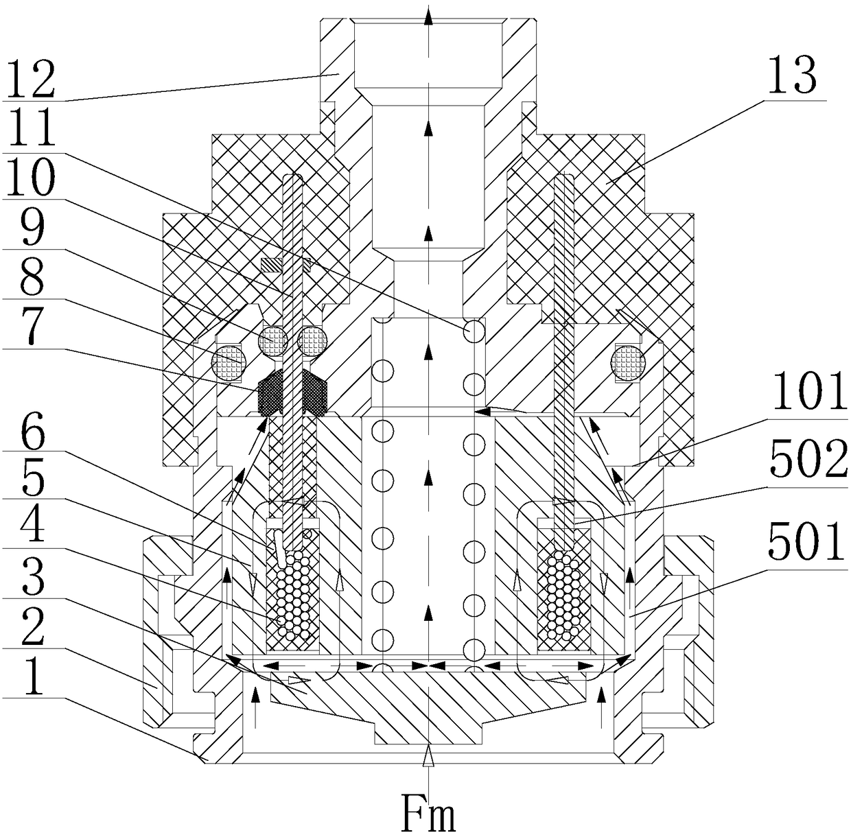
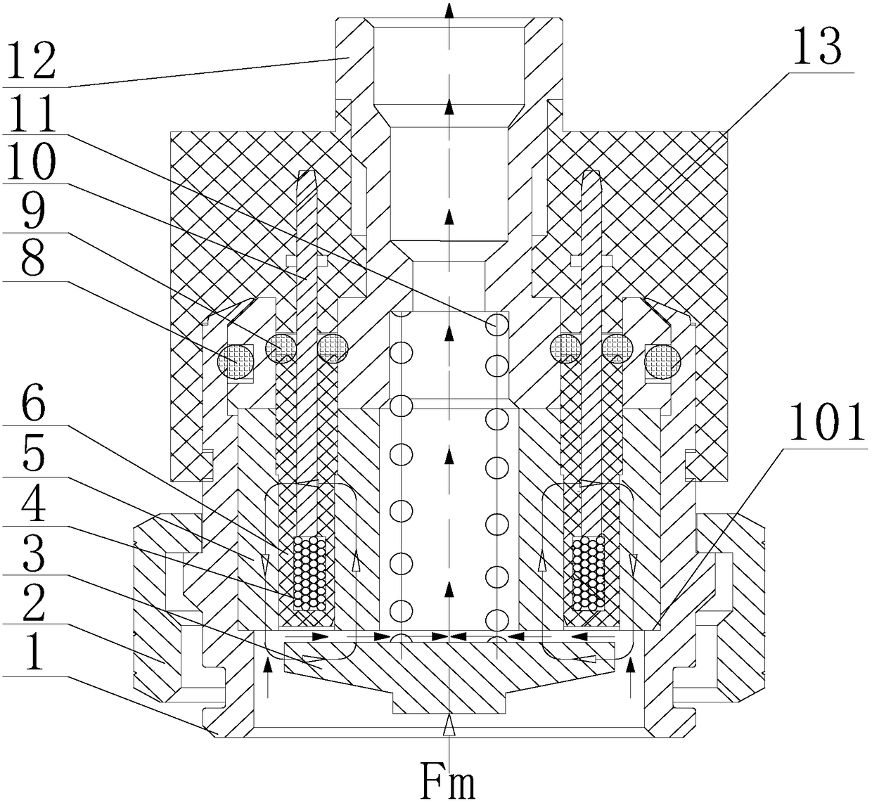
[0018] refer to figure 1 . In the embodiment described below, a heat-insulated and sealed electromagnet assembly mainly includes an electromagnet housing 1 with a multi-stage diameter and a concentric cavity cavity with a multi-stage diameter, which is concentrically assembled in the electromagnet case The outside of the body 1 acts as a fastening nut 2 for fixing the electromagnet, and the iron core 5 and the electromagnet spring 11 assembled in the central cavity of the electromagnet housing 1 are axially positioned at the port of the cavity of the inner frame 12 and the armature The coil bobbin 6 between 3 covers the coil 4, and the coil 4 covered by the coil bobbin 6 is assembled in the groove of the iron core 5 opening downward, and the two connecting rods 10 respectively connected to the two ends of the wires of the coil 4, The upper end surface of the iron core 5 is close to the lower end surface of the inner frame 12, the cylindrical shoulder blade surface formed on ...


PUM


Abstract

The invention discloses a thermal isolation and sealing electromagnet assembly, and aims to provide the thermal isolation and sealing electromagnet assembly which can be used for eliminating influence of assembly stress on magnetic permeability of an electromagnet and can be used for fully cooling an inner surface and an outer surface of an iron core. The thermal isolation and sealing electromagnet assembly is achieved according to the following technical scheme: a cylindrical table shoulder is arranged on an iron core (5) and is used for making a press part of an upper end of the iron core (5) far away from a path passed by main flux of the electromagnet, a gap (501) is reserved between the diameter of a low cylinder and the diameter of an inner hole of an electromagnet shell (1), a gap (502) is reserved in the top of a groove of a coil framework (6) and the iron core (5) and is used for the coil framework to be expanded, so that fuel oil can flow out of a central hole of the iron core and also can flow out of the gap (501) which is formed between an outer surface of the iron core and an inner surface of the electromagnet shell (1) and is provided with annular fuel oil flowing, the fuel oil flows through both of the inner surface and the outer surface of the iron core, and the iron core can be fully cooled.

Description

technical field [0001] The present invention relates to an electromagnet assembly mainly used in a high-pressure fuel injection device. Background technique [0002] With the increasing global warming and environmental pollution, countries have increasingly high requirements for the treatment of vehicle exhaust, especially diesel vehicle exhaust. In order to reduce the emission of pollutants such as NOx, particulate matter, HC and CO, the diesel engine requires the fuel injection system to realize precise control of high pressure, multiple injections, fuel injection quantity and fuel injection time, especially for the time of multiple injections in microseconds, Meeting the above requirements can only be achieved by using electronic control technology, so it is very important to improve the response speed of the electronic control system. The bottleneck of improving the response speed of the electronic control system is to improve the response speed of the actuator. There ...

Claims


Application Information

Patent Timeline
Patent Type & Authority Patents(China)
IPC IPC(8): H01F7/127H01F7/128H01F27/30H01F27/26H01F27/12
CPCH01F7/127H01F7/128H01F27/12H01F27/266H01F27/306
Inventor 宋厚杭姚守理蔡林峰龙再冬徐刚薛莹莹
Owner 成都威特电喷有限责任公司
Why Eureka
Try Eureka