Substrate temperature monitoring device, dry etching equipment and substrate temperature monitoring method

A monitoring device and substrate technology, which is applied in semiconductor/solid-state device testing/measurement, electrical components, semiconductor/solid-state device manufacturing, etc., can solve the problems of general thermal conductivity, waste of production cost, roughness and inequality, and avoid the Mla phenomenon Effect

Inactive Publication Date: 2016-12-07
BOE TECH GRP CO LTD +1
View PDF5 Cites 6 Cited by
  • Summary
  • Abstract
  • Description
  • Claims
  • Application Information

AI Technical Summary

Problems solved by technology

[0003] There are following problems in the above-mentioned dry etching process: figure 2 As shown, the surface of the top of the lower electrode 1 is rough and uneven when it is first used. At this time, the top of the lower electrode 1 is in point contact with the substrate 2. The thermal conductivity of the top of the lower electrode 1 is average, and the heat loss on the substrate 2 is relatively low. Therefore, the temperature difference between the area corresponding to the top of the lower electrode 1 on the substrate 2 (hereinafter referred to as the contact area) and the surrounding area not corresponding to the top of the lower electrode 1 (hereinafter referred to as the non-contact area) is not much different.
Although this countermeasure can alleviate the above-mentioned Mla phenomenon to a certain extent, due to the different characteristics of different products and the different stability of the production line process, it is not easy to grasp the time to clean or replace the lower electrode. If the replacement cycle is short, it will cause a decrease in work efficiency and unnecessary waste of production costs, and if the cleaning or replacement cycle is long, the above-mentioned Mura phenomenon cannot be effectively alleviated.

Method used


Image

  • Substrate temperature monitoring device, dry etching equipment and substrate temperature monitoring method
  • Substrate temperature monitoring device, dry etching equipment and substrate temperature monitoring method
  • Substrate temperature monitoring device, dry etching equipment and substrate temperature monitoring method

Examples


Embodiment 1

[0055] like Figure 4 As shown, this embodiment provides a substrate temperature monitoring device 3, the substrate temperature monitoring device 3 includes a temperature sensing module 31 and a difference calculation module 32, wherein the temperature sensing module 31 is installed in the etching process of the etching equipment Inside the chamber, it is used to sense the temperature of each area on the substrate in the etching chamber in real time during etching; the difference calculation module 32 is used to calculate the temperature on the substrate according to the temperature of each area on the substrate sensed by the temperature sensing module 31. The temperature difference between each contact area and its surrounding non-contact area.

[0056] It should be noted that the "contact area" mentioned in this embodiment refers to the area on the substrate corresponding to the lower electrode in the etching chamber during etching, that is, the area on the substrate that is...

Embodiment 2

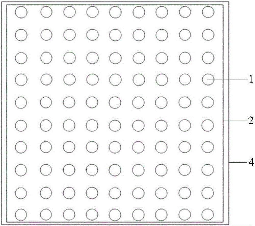
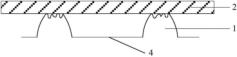
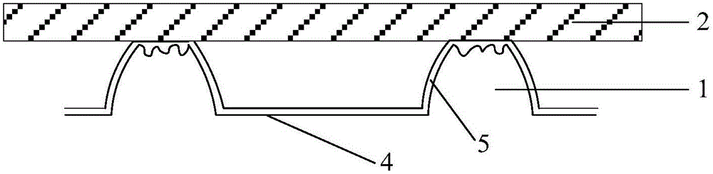
[0077] Based on Embodiment 1, this embodiment provides a dry etching equipment, such as Figure 15 As shown, the dry etching equipment includes: an etching chamber 6, a base 4 disposed below the interior of the etching chamber 6, a plurality of lower electrodes 1 disposed on the base 4, disposed above the etching chamber 6 The upper electrode 7, and the substrate temperature monitoring device as described in the first embodiment.

[0078] exist Figure 15 Only some components in the substrate temperature monitoring device are exemplarily shown in the figure: a plurality of infrared temperature sensors 311 installed on the upper part of the inner wall of the etching chamber 6, and a heating device 36 arranged inside each lower electrode 1, wherein The infrared temperature sensor 311 is used to sense the temperature of each area on the substrate 2 in real time during etching, and the heating device 36 is used to perform temperature compensation on the contact area on the substr...

Embodiment 3

[0081] This embodiment provides a substrate temperature monitoring method, the substrate temperature monitoring method includes the following steps:

[0082] Real-time sensing the temperature of each area on the substrate in the etching chamber during etching;

[0083] calculating the temperature difference between each contact area on the substrate and its surrounding non-contact area according to the sensed temperature of each area on the substrate;

[0084] Wherein, the contact area is an area on the substrate corresponding to the lower electrode in the etching chamber during etching, and the non-contact area is an area on the substrate not corresponding to the lower electrode during etching.

[0085] The beneficial effects of the substrate temperature monitoring method provided in this embodiment are the same as those of the substrate temperature monitoring device provided in Embodiment 1, and will not be repeated here.

[0086] As a preferred option, such as Figure 16 ...


PUM


Abstract

The invention provides a substrate temperature monitoring device, dry etching equipment and a substrate temperature monitoring method, and relates to the technical field of dry etching, in order to relieve or avoid the Mladic phenomenon caused by temperature difference in different areas on a substrate, and prevent the reduction of the working efficiency and unnecessary wastes of the production cost. The substrate temperature monitoring device comprises: a temperature sensing module mounted in an etching chamber of the etching equipment and used for sensing temperatures of various areas on a substrate in the etching chamber in an etching process; and a difference calculation module connected with the temperature sensing module and used for calculating temperature differences of contact areas and peripheral noncontact areas on the substrate according to the temperatures of the areas on the substrate sensed by the temperature sensing module. The substrate temperature monitoring device is used for monitoring the temperature distribution condition of the substrate in the etching process in real time.

Description

technical field [0001] The invention relates to the technical field of dry etching, in particular to a substrate temperature monitoring device, dry etching equipment and a substrate temperature monitoring method. Background technique [0002] Dry etching (Dry Etch) process is an indispensable process in the field of TFT-LCD (Thin Film Transistor Liquid Crystal Display, Thin Film Transistor Liquid Crystal Display), the main function of dry etching process is to remove a part of the film on the substrate, in order to The desired pattern is formed in the film. The dry etching equipment used in the dry etching process mainly includes: an etching chamber, such as figure 1 As shown, the lower part of the etching chamber is provided with a base 4 for placing the substrate 2, the upper surface of the base 4 has a plurality of protruding lower electrodes 1, and the upper part of the etching chamber is provided with an upper electrode. During etching, the substrate 2 is placed on th...

Claims


Application Information

Patent Timeline
Patent Type & Authority Applications(China)
IPC IPC(8): H01L21/66H01L21/67
CPCH01L21/67069H01L21/67248H01L22/12
Inventor 王明超王俊伟
Owner BOE TECH GRP CO LTD
Why Eureka
Try Eureka