
Fixed device of permanent magnet and permanent-magnet motor

A technology of fixing devices and permanent magnets, which is applied in the direction of magnetic circuit rotating parts, magnetic circuit shape/style/structure, etc., can solve the problems of difficult to grasp bolt torque, increase magnetic loss, inconvenient assembly, etc., and achieve simple and reliable installation and fixation , Prevent movement, simple structure

Inactive Publication Date: 2016-12-07
CSR ZHUZHOU ELECTRIC CO LTD
View PDF6 Cites 1 Cited by
  • Summary
  • Abstract
  • Description
  • Claims
  • Application Information

AI Technical Summary

Problems solved by technology

The magnetic pole box structure is fixed and reliable, and the experience is mature, but the outer diameter of the rotor with the box structure increases accordingly, and the hysteresis loss is relatively large, especially for the fixed pole box structure of large permanent magnets. The magnetic loss is reduced, and the permanent magnet is not easy to dissipate heat, and it is also difficult to apply to the large permanent magnet
[0004] Now there is also a structure for mechanically fixing the permanent magnet. The most common method is to drill holes in the permanent magnet and fix it with bolts. However, this structure is difficult to operate in practice. It is not convenient to install again; there are also permanent magnets fixed by accessories, but the general structure is complicated, and the actual assembly is inconvenient

Method used


Image

  • Fixed device of permanent magnet and permanent-magnet motor
  • Fixed device of permanent magnet and permanent-magnet motor
  • Fixed device of permanent magnet and permanent-magnet motor

Examples


Embodiment Construction

[0024] The core of the present invention is to provide a permanent magnet fixing device whose structural design can make the installation and fixing of the permanent magnet simple and reliable. Another core of the present invention is to provide a permanent magnet motor comprising the above permanent magnet fixing device.

[0025] In order to enable those skilled in the art to better understand the solution of the present invention, the present invention will be further described in detail below in conjunction with the accompanying drawings and specific embodiments.

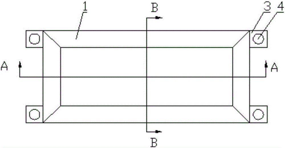
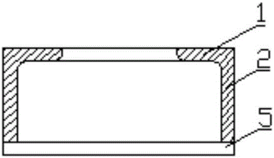
[0026] Please refer to Figure 1 to Figure 3 , figure 1 It is a structural schematic diagram of a specific embodiment of the permanent magnet fixing device provided by the present invention; figure 2 for figure 1 A-A sectional view of A-A; image 3 for figure 1 Sectional view of B-B section. .

[0027] The permanent magnet fixing device provided by the specific embodiment of the present invention includes...


PUM


Abstract

The invention discloses a fixed device of a permanent magnet. The fixed device comprises a cover body, wherein the cover body covers the permanent magnet to make the permanent magnet fixed on a rotor and comprises a rectangular-ambulatory-plane top plate and side plates, the rectangular-ambulatory-plane top plate is fixedly connected, and the side plates encircle the top plate; when the fixed device is used, the cover body covers the permanent magnet, the permanent magnet can be pressed on the rotor by the rectangular-ambulatory-plane top plate and is prevented from being disconnected with the rotor, the permanent magnet can be circumferentially fixed by the side plates and is prevented from moving, a rectangular-ambulatory-plane gap can be formed in the periphery of the top of the permanent magnet and is matched with the rectangular-ambulatory-plane top plate, a top surface of the permanent magnet can be flush with an external plate surface of the top plate, an air gap is reduced, the external diameter size of the rotor is reduced, the magnetic hysteresis loss is reduced, and the magnetic field utilization ratio is improved. Therefore, the fixed device of the permanent magnet, provided by the invention, is simple in structure, and the permanent magnet can be simple and reliable to install and fix. The invention also discloses a permanent magnet motor comprising the abovementioned fixed device of the permanent magnet.

Description

technical field [0001] The invention relates to the field of installation of permanent magnets, in particular to a fixing device for permanent magnets. In addition, the present invention also relates to a permanent magnet motor comprising the above permanent magnet fixing device. Background technique [0002] A permanent magnet motor is a motor in which a magnetic field is established by one or more permanent magnets. It has the advantages of simple structure, low loss and convenient control, so its application fields are becoming more and more extensive. However, the shedding of permanent magnets is also an obstacle to the development of permanent magnet motors, and the fixing effect of permanent magnets has become one of the key factors affecting the service life of permanent magnet motors. [0003] For the fixing of the permanent magnets of the inner rotor permanent magnet motor, the magnetic pole box structure is generally adopted, or the permanent magnets are directly ...

Claims


Application Information

Patent Timeline
IPC IPC(8): H02K1/27
CPCH02K1/27
Inventor 梁双全龚天明李志鹏刘志恒王晓慧仇超武
Owner CSR ZHUZHOU ELECTRIC CO LTD
Learn More