
Circuit board

A circuit board and circuit technology, applied in the directions of printed circuit, multilayer circuit manufacturing, printed circuit manufacturing, etc., can solve the problems of increasing production process and cost, affecting the passage of light, imaging alignment deviation, etc., and achieving easy positioning welding Forming, the effect of reducing production processes and costs

Inactive Publication Date: 2016-12-07
苏州良基电子科技有限公司
View PDF8 Cites 1 Cited by
  • Summary
  • Abstract
  • Description
  • Claims
  • Application Information

AI Technical Summary

Problems solved by technology

The previous process method used imaging alignment, and the multi-layer circuit board structure would affect the passage of light, which caused deviations in imaging alignment, so it was necessary to cut the circuit board to reduce the thickness of the circuit board, which also limited the material of the circuit board. thus increasing the production process and cost

Method used


Image

  • Circuit board
  • Circuit board

Examples


Embodiment Construction

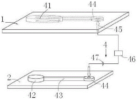
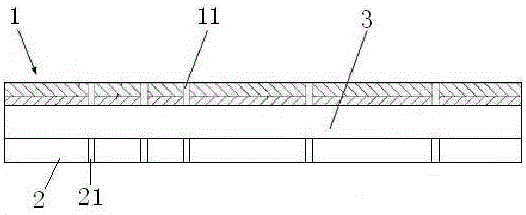
[0014] refer to figure 1 , 2 , a circuit board, including a first circuit board 1, a second circuit board 2, an adhesive layer 3 is coated between the first circuit board 1 and the second circuit board 2, specifically, a hot-pressing soldering method is adopted The first circuit board 1 and the second circuit board 2 are consolidated together with an adhesive layer 3 to form a circuit board. Further, the first circuit board 1 is provided with a plurality of first positioning connection holes 11, and the second circuit board 2 A number of second positioning connection holes 21 are opened on the top, and a positioning device 4 is installed on the first circuit board 1 and the second circuit board 2. The positioning device 4 includes an external power terminal 41, an internal power terminal 42, a connecting rod 43, and a positioning device. Block 44, connecting wire 45, current indicating meter 46, power supply 47, external energizing terminal 41 and internal energizing terminal...


PUM


Abstract

The invention discloses a circuit board. The circuit board comprises a first circuit board body and a second circuit board body. The portion between the first circuit board body and the second circuit board body is coated with a bonding layer, a positioning device is positioned and installed on the first circuit board body and the second circuit board body, and the first circuit board body is in contact with the second circuit board body to form a cut-off circuit with the positioning device. The positioning device comprises an external energizing terminal, an internal energizing terminal, connecting rods, positioning blocks, a communication wire, a current indicating gauge and a power source; the external energizing terminal and the internal energizing terminal are fixedly connected with the connecting rods and the positioning blocks to form two sections to be matched with a positioning module; the positioning blocks are connected with the current indicating gauge and the power source through the communication wire to form a circuit. According to the circuit board, the space position of the circuit board is accurately positioned through the positioning device, later positioning, welding and forming are easy, and therefore the production process and the cost are reduced.

Description

technical field [0001] The invention relates to a circuit board. Background technique [0002] The circuit board is an important part of an electronic product. Multiple boards are usually welded together by hot pressing and melting to form a circuit board. Before welding, the welded boards need to be aligned. The previous process method used imaging alignment, and the multi-layer circuit board structure would affect the passage of light, which caused deviations in imaging alignment, so it was necessary to cut the circuit board to reduce the thickness of the circuit board, which also limited the material of the circuit board. Thereby increasing the production process and cost. Contents of the invention [0003] The invention aims at the deficiencies of the prior art, and provides a circuit board which can be easily positioned and welded to form by limiting the relative position of the circuit board through the cooperative positioning of the positioning device. [0004] In...

Claims


Application Information

Patent Timeline
Patent Type & Authority Applications(China)
IPC IPC(8): H05K1/02H05K3/46
CPCH05K1/0268H05K3/4638H05K2201/20
Inventor 王鹏
Owner 苏州良基电子科技有限公司
Learn More