Knot disengaging mechanism and method of knotter

A knotter and detachment technology, applied in the application field of knotter, can solve problems such as equipment damage, achieve production efficiency guarantee, reduce the process of manual grinding of contact surfaces, and reduce the effect of unsmooth detachment

Inactive Publication Date: 2016-12-14
BEIJING HANGXING MACHINERY MFG CO LTD
View PDF5 Cites 3 Cited by
  • Summary
  • Abstract
  • Description
  • Claims
  • Application Information

AI Technical Summary

Problems solved by technology

[0004] In order to improve the use reliability of the knotter, reduce the difficulty of assembly, and improve the interchangeability of parts, the present invention discloses a method for forced unknotting of the knotter, aiming to provide a method capable of forcibly unknotting to solve the problem of The problem of equipment damage caused by the knotting of the knotter due to the failure of unknotting

Method used


Image

  • Knot disengaging mechanism and method of knotter
  • Knot disengaging mechanism and method of knotter
  • Knot disengaging mechanism and method of knotter

Examples


Embodiment Construction

[0018] Below, the present invention will be further described in conjunction with the accompanying drawings and specific embodiments.

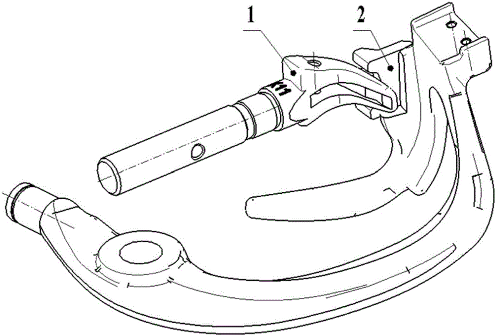
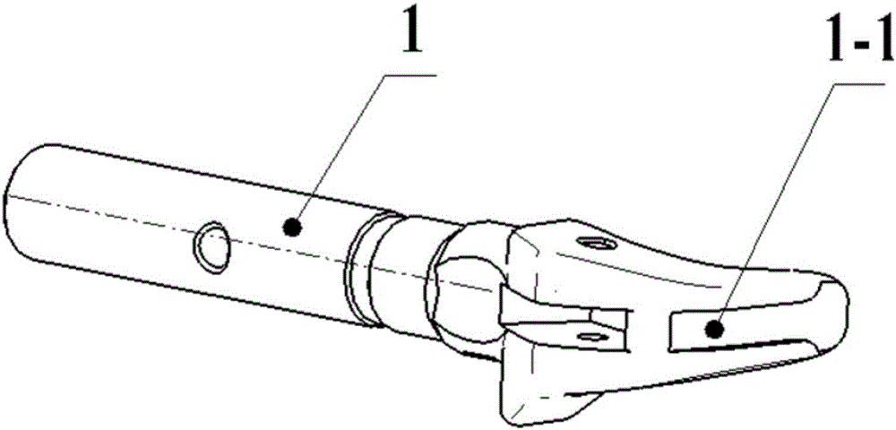
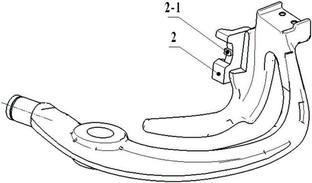
[0019] The realization of the unknotting mechanism and the unknotting method: such as figure 1 , 2 as shown,

[0020] A long groove 1-1 is processed on the arc-shaped back of the knotting nozzle 1, and a protrusion 2-1 is processed on the original contact surface of the tool holder 2 with the knotting nozzle 1, and the width is wider than the groove 1-1 Slightly narrow, when assembled, the top of the protrusion 2-1 does not contact the bottom of the groove 1-1, the protrusion 2-1 can move along the groove 1-1, and the two can move relatively freely without interference or jamming.

[0021] When knotting, drive the knotting nozzle 1 to rotate around its own rotation axis to tie the knot. At this time, the knot is wrapped around the knotting nozzle 1, and then drive the knife rest 2 to rotate again, so that the protrusion 2 on the knife rest 2...


PUM


Abstract

The invention discloses a knot disengaging mechanism and method of a knotter. The knot disengaging mechanism of the knotter comprises a knotter jaw and a tool rest, a long groove is machined in the circular-arc-shaped ridge of the knotter jaw, the matching surface of the tool rest with the circular-arc-shaped ridge of the knotter jaw is provided with a protrusion, and the protrusion is matched with the groove and can move along the groove. According to the knot disengaging mechanism and method of the knotter, optimization and improvement are conducted on the tool rest and the knotter jaw part, an original knot disengaging mode is changed, mutual contact friction of the tool rest and the knotter jaw is avoided in the knot disengaging process, and the purposes of reducing abrasion of related structures and forcefully disengaging a knot are achieved. The use reliability of the knotter is improved, the assembly difficulty is reduced, the interchangeability of parts is improved, and the knot formation rate of the knotter is guaranteed. The knot disengaging mechanism and method of the knotter are mainly applied to the field of knotter application.

Description

technical field [0001] The invention relates to a knotting mechanism and a knotting method for a knotter, and more specifically to a knotting mechanism and a knotting method for a knotter, which are mainly used in the application field of knotters. Background technique [0002] The knotter is the core component of the rope baler. It is used to tie the bundled crop straw into knots. The knot forming rate and reliability requirements are very high. Multiple simultaneous work to complete the bundling requires a high bundling rate of the whole machine, so higher requirements are put forward for the knotting ratio of a single knotter. At present, the knotting process of the knotter is to rely on the relative friction and sliding of the knife rest and the knotting mouth to separate the knot from the knotting mouth. During the whole process, the knife rest and the knotting mouth are always in contact, and there is a certain amount of friction force. [0003] This will bring three...

Claims


Application Information

Patent Timeline
Patent Type & Authority Applications(China)
IPC IPC(8): A01F15/14
CPCA01D59/04A01F15/14A01F15/145
Inventor 王彬郭磊张广超
Owner BEIJING HANGXING MACHINERY MFG CO LTD
Why Eureka
Try Eureka