Automatic groove cleaning machine for motor stator inner groove
What is Al technical title?
Al technical title is built by PatSnap Al team. It summarizes the technical point description of the patent document.
A motor stator, automatic cleaning technology, applied in the direction of electric components, manufacturing motor generators, manufacturing stator/rotor body, etc., can solve the problems of harmful dust harmful to health, unstable quality, high labor intensity, etc., to achieve easy installation and adjustment, Small size, high cleaning effect
Active Publication Date: 2016-12-14
ANSTEEL GRP MINING CO LTD
View PDF7 Cites 12 Cited by
Summary
Abstract
Description
Claims
Application Information
AI Technical Summary
This helps you quickly interpret patents by identifying the three key elements:
Problems solved by technology
Method used
Benefits of technology
Problems solved by technology
[0003] The purpose of the present invention is to provide an automatic cleaning machine for the inner groove of the motor stator, which solves a series of problems such as hidden safety hazards, harmful dust harmful to health, high labor intensity and unstable quality caused by manual cleaning of the inner groove of the motor stator. Greatly improve work efficiency and cleaning quality
Method used
Image
Click on the blue label to locate the original text in one second.
Reading with bidirectional positioning of images and text.
Examples
Embodiment Construction
[0022] The specific implementation manner of the present invention will be further described below in conjunction with the accompanying drawings.
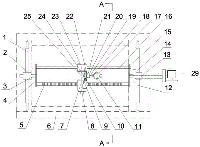
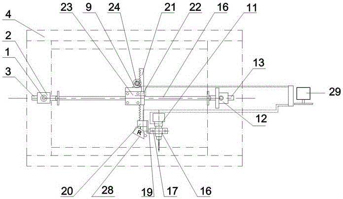
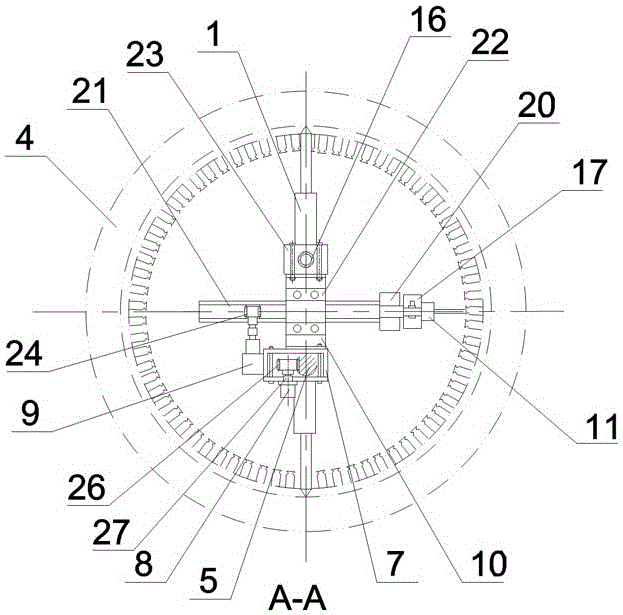
[0023] Such as figure 1 , 2, and 3, the automatic slot cleaning machine for the inner groove of the motor stator of the present invention consists of a bidirectional left pneumatic strut 1 and a bidirectional right pneumatic strut 12 arranged in the inner groove of the motor stator 6, and the two ends are respectively connected with the bidirectional The left pneumatic strut 1 and the two-way right pneumatic strut 12 are connected to the slewing bracket, the longitudinal moving device set on the slewing bracket, the radial moving device set on the longitudinal moving device, set on the radial moving device The slot-clearing electric drill 11 and the electric control device 29 are formed. After starting the two-way left pneumatic strut 1 and the two-way right pneumatic strut 12, the whole rotary bracket is fixed in the inner groove ...
PUM
Abstract
The invention belongs to the technical field of motor maintenance and particularly relates to an automatic groove cleaning machine for a motor stator inner groove. The automatic groove cleaning machine is composed of a bidirectional left pneumatic supporting rod, a bidirectional right pneumatic supporting rod, a rotation support, a longitudinal moving device, a radial moving device, a groove removing electric drill and an electric control device. The rotation support is composed of a left fixing sleeve, a left rotating shaft, a left baffle, a longitudinal linear rail, a longitudinal rack, a right baffle, an electric indexer and a right fixing sleeve. The longitudinal moving device is composed of a sliding block, a drive support, a drive box, a longitudinal drive motor and a longitudinal drive gear. The radial moving device is composed of a radial rack, an end head frame, a connecting plate, a clamping plate, an adjusting fastening ring, a radial drive motor and a U-shaped pressing plate. A groove cleaning drill bit of the automatic groove cleaning machine has freedom degrees in several directions including the longitudinal direction, the radial direction and the circumferential direction, any part in the motor stator inner groove can be cleaned, the work process is automatic, the trouble of manual work is solved, and the effect is improved by several times.
Description
technical field [0001] The invention belongs to the technical field of motor maintenance, and in particular relates to an automatic slot cleaning machine for an inner slot of a motor stator. Background technique [0002] The AC motor is mainly composed of a stator and a rotor. The stator is a cylindrical barrel-shaped structure with grooves on the inner surface for installing stator coils. The stator coils are wrapped by insulating materials in the grooves and sealed with insulating varnish to play a role. Insulation, fixation, and dustproof functions. There are often motors that are damaged due to burnt stator coils. The high temperature when the stator coils are burned causes oxidative denaturation of insulating varnish and insulating materials, and also makes the stator coils form residual dirt such as metal oxides and metal particles. This residual dirt is hard, poisonous, and has strong adhesion, and it is attached to the wire groove of the stator, so it is difficult t...
Claims
Application Information
Patent Timeline
Application Date:The date an application was filed.
Publication Date:The date a patent or application was officially published.
First Publication Date:The earliest publication date of a patent with the same application number.
Issue Date:Publication date of the patent grant document.
PCT Entry Date:The Entry date of PCT National Phase.
Estimated Expiry Date:The statutory expiry date of a patent right according to the Patent Law, and it is the longest term of protection that the patent right can achieve without the termination of the patent right due to other reasons(Term extension factor has been taken into account ).
Invalid Date:Actual expiry date is based on effective date or publication date of legal transaction data of invalid patent.