
Discharge device of glass tube cleaning machine

A discharge device and glass tube technology, applied in the direction of cleaning hollow objects, cleaning methods and utensils, chemical instruments and methods, etc., can solve the problems of water not being scraped clean, glass tube damage, etc., to achieve better working conditions and stable quality Effect

Inactive Publication Date: 2016-12-14
HAINING XINYU SOLAR ENERGY EQUIP
View PDF7 Cites 1 Cited by
  • Summary
  • Abstract
  • Description
  • Claims
  • Application Information

AI Technical Summary

Problems solved by technology

Because the glass tube is often deviated, the wiper rubber ring will be separated from the glass tube so that the water on the glass tube cannot be wiped clean; the severe one will cause the glass tube to be damaged.

Method used


Image

  • Discharge device of glass tube cleaning machine
  • Discharge device of glass tube cleaning machine
  • Discharge device of glass tube cleaning machine

Examples


Embodiment 1

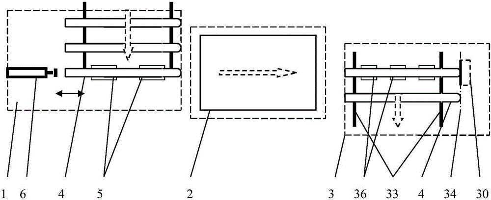
[0015] Example 1, the glass tube automatic cleaning equipment with an electric cleaning cylinder includes a feeding mechanism 1, a cleaning device 2 and a discharging device 3; the feeding mechanism 1, the cleaning device 2 and the discharging device 3 move according to the movement of the cleaned glass tube. The paths are laid out sequentially.

[0016] The feeding mechanism 1 includes two feeding rollers 5, a pneumatic feeding propeller 6 and a feeding sensor 7 arranged one after the other along the moving direction of the glass tube 4; Matching semicircular concave surface; the glass tube 4 enters the feed roller 5, and the feed sensor 7 outputs a signal to make the pneumatic feed pusher 6 complete a push / reset action.

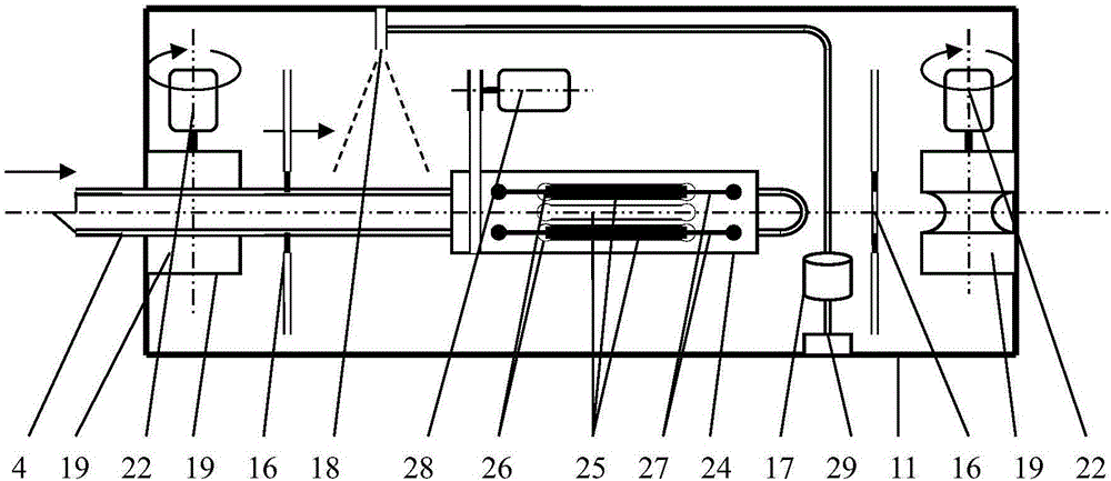
[0017] The cleaning device 2 includes a spray tank body 11, two sets of rubber wheel driving mechanisms 12 and 13 arranged along the axis of the cleaning device 2, an electric cleaning cylinder 14, and a wiper located between the two sets of rubber wheel dr...


PUM


Abstract

The invention discloses an automatic glass tube cleaning device with an electric cleaning cylinder. The automatic glass tube cleaning device comprises a feeding mechanism, a cleaning device and a discharge device, wherein the feeding mechanism comprises feeding supporting wheels, a pneumatic feeding thruster and a feeding sensor; the cleaning device comprises a spraying tank body, rubber wheel driving mechanisms, a wiping rubber ring, the electric cleaning cylinder, a circulating pump and a nozzle; each rubber wheel driving mechanism comprises two rubber wheels which are symmetrically arranged on the upper and lower sides of the axis of the cleaning device; the rubber wheel driving mechanisms have electric driving parts; the electric cleaning cylinder comprises a cylinder of which the inner diameter is 20 to 60 millimeters larger than the outer diameter of the glass tubes; a plurality of long through holes are uniformly distributed in the surface of the cylinder; folded elastic scouring pads are inserted into the long through holes at intervals; and the cylinder and the cleaning device are coaxial and are in transmission connection with a driving motor. According to the automatic glass tube cleaning device, the electric cleaning cylinder is adopted to cleaning the glass tubes, one feeding worker and about 0.6 discharge worker can be decreased, and the cleaning quality of the glass tubes is more stable.

Description

technical field [0001] The invention relates to a discharging device of a glass tube cleaning machine. Background technique [0002] To produce all-glass vacuum collector tubes, the inner glass tube needs to be cleaned with deionized water before coating. The prior art employs two workers, one feeding worker is responsible for pushing the glass tube into the glass tube cleaning device, and the other discharging worker is responsible for pulling out the glass tube after being sprayed and cleaned in the spray tank. Since there is often a deviation in pulling out the glass tube, the wiper rubber ring is separated from the glass tube, so that the water on the glass tube cannot be wiped clean; in severe cases, the glass tube is damaged. SUMMARY OF THE INVENTION [0003] The purpose of the present invention is to provide a discharge device for a glass tube cleaning machine. [0004] The technical scheme of the present invention to achieve its purpose is to manufacture a glass ...

Claims


Application Information

Patent Timeline
IPC IPC(8): B08B9/023
CPCB08B9/023
Inventor 潘宇东
Owner HAINING XINYU SOLAR ENERGY EQUIP
Learn More