Protective film cutting tool

A protective film and cutting technology, which is applied in metal processing and other directions, can solve the problems of poor consistency of the protective film angle, burrs on the corners after cutting, and reduced viscosity, etc., to achieve the effects of convenient operation, improved cutting efficiency, and low cost

Active Publication Date: 2016-12-14
GOERTEK INC
View PDF6 Cites 2 Cited by
  • Summary
  • Abstract
  • Description
  • Claims
  • Application Information

AI Technical Summary

Problems solved by technology

[0007] In view of the above problems, the purpose of the present invention is to provide a protective film cutting tool to solve the pro...

Method used


Image

  • Protective film cutting tool
  • Protective film cutting tool
  • Protective film cutting tool

Examples


Embodiment Construction

[0038] In the following description, for purposes of explanation, numerous specific details are set forth in order to provide a thorough understanding of one or more embodiments. It may be evident, however, that these embodiments may be practiced without these specific details.

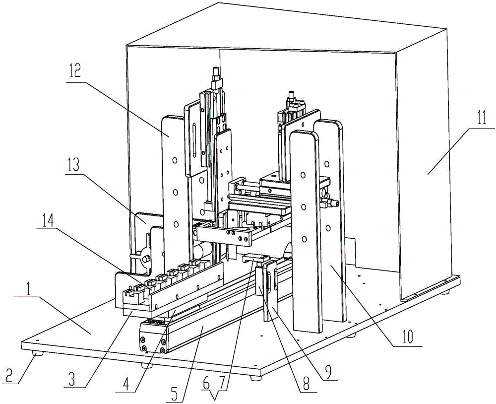
[0039] In view of the various problems in the manual film cutting proposed above, the present invention proposes a protective film cutting tool. The equipment provided by the present invention can realize the cutting of protective films on different end faces. The equipment is simple in structure, low in cost, and easy to operate. It can be extended to the cutting of protective films similar to end faces of different shapes.

[0040] Specific embodiments of the present invention will be described in detail below in conjunction with the accompanying drawings.

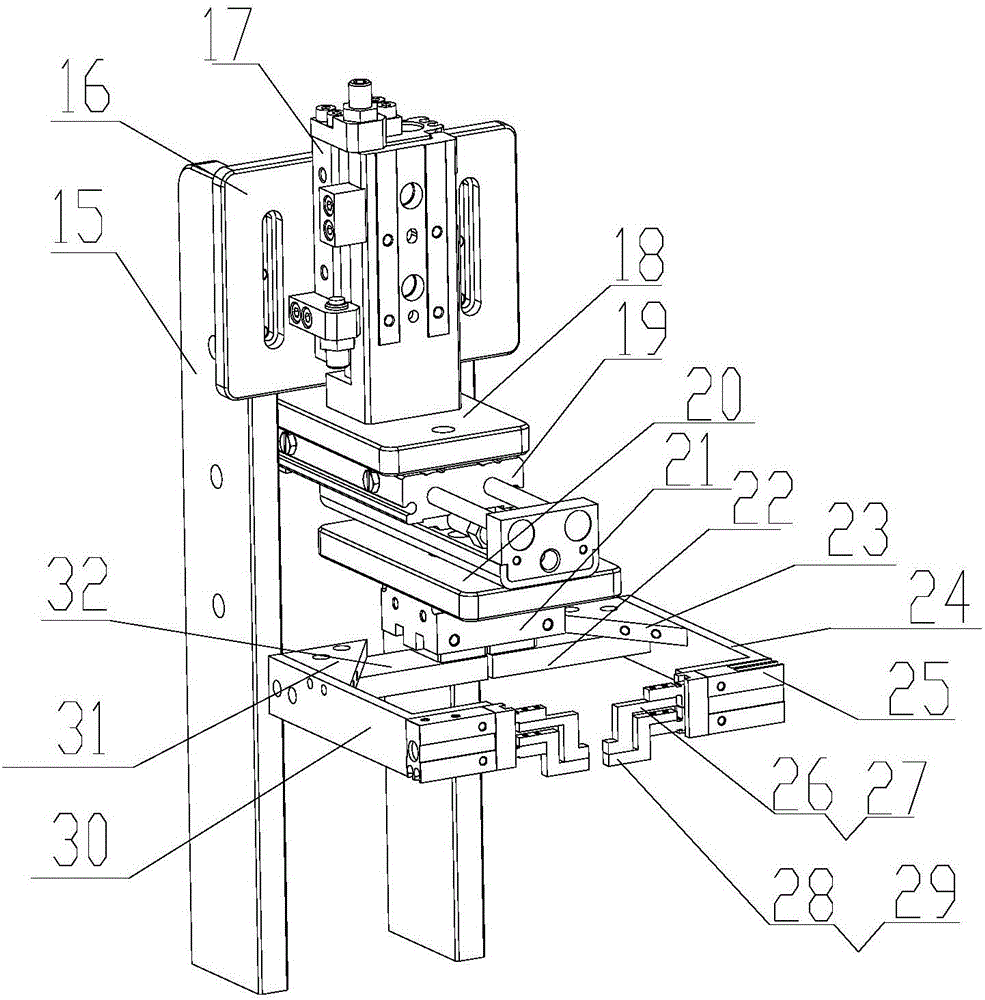
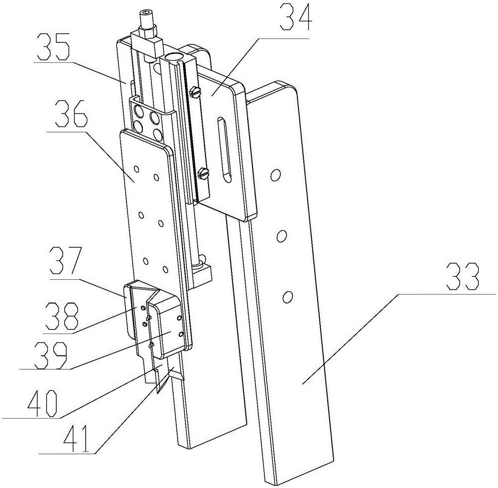
[0041] In order to illustrate the structure of the protective film cutting tool provided by the present invention, Figure 1 to Figure 5 The ...


PUM


Abstract

The invention provides a protective film cutting tool. The protective film cutting tool comprises a bottom plate, an air cylinder fixing plate, an electric cylinder, a clamping jaw mechanism, a tool rest mechanism and a protective film placing mechanism, wherein the air cylinder fixing plate is arranged on the upper surface of the bottom plate; a protective film pasting circulating seat is arranged above the electric cylinder, an air cylinder is arranged on the air cylinder fixing plate, and a pressing plate is arranged above the air cylinder; and the protective film pasting circulating seat is driven to move to the protective film placing mechanism by the electric cylinder, one end of a protective film in the protective film placing mechanism is pulled to the position above the protective film pasting circulating seat by the clamping jaw mechanism, the pressing plate is driven to press and limit the protective film on the protective film pasting circulating seat by the air cylinder, and then the protective film in the protective film placing mechanism is clamped by the clamping jaw mechanism, so that the protective film clamped by the clamping jaw mechanism and the protective film limited on the protective film pasting circulating seat are tightened, and the protective film which is pressed and limited is cut by the tool rest mechanism. By utilizing the protective film cutting tool, the problems of bad consistency of angles of the protective film, burrs at corners after cutting, low viscosity and the like in a film cutting process can be solved.

Description

technical field [0001] The invention relates to the technical field of film cutting, and more specifically, to a protective film cutting tool. Background technique [0002] At present, protective films are widely used in various industries. In order to achieve certain specific functions, the end faces of protective films are generally cut into different shapes. Among them, the commonly used method in the film cutting process in the industry is to directly cut it into a predetermined shape by hand with a blade. The main disadvantages of manual cutting are: [0003] (1) During the cutting process, due to human reasons, the consistency of the cutting angle is poor. [0004] (2) There will be burrs on the corners after cutting, which will affect the normal use. [0005] (3) The protective film needs to be unfolded during the cutting process, so the viscosity of the protective film is reduced. [0006] In order to solve the above problems, the present invention proposes a pro...

Claims


Application Information

Patent Timeline
IPC IPC(8): B26D1/06B26D7/02B26D7/26B26D5/12B26D7/14
CPCB26D1/065B26D5/12B26D7/015B26D7/025B26D7/14B26D7/2614
Inventor 赵善永王鑫李树武
Owner GOERTEK INC
Why Eureka
Try Eureka