Inner tube automatic splicing system

An automatic splicing and inner tube technology, which is applied to tubular items, household appliances, other household appliances, etc., can solve the problems of many uncontrollable factors, increased labor costs, and high scrap rate, so as to avoid a large number of uncontrollable factors and achieve consistent improvement. performance and quality, the effect of reducing the footprint

Active Publication Date: 2018-12-21
ZHEJIANG GUOZI ROBOT TECH
View PDF9 Cites 0 Cited by
  • Summary
  • Abstract
  • Description
  • Claims
  • Application Information

AI Technical Summary

Problems solved by technology

[0002] With the development of society, the cost of labor in factories continues to increase, and at the same time, human resources are becoming more scarce. However, the automation of inner tube splicing is currently very low in the entire industry and requires a large number of workers to operate.
After the inner tube is cut from the injection molding machine, it not only needs to be manually unloaded, but also needs a large number of material accumulation trolleys for transfer. Due to the inconsistency of manual operation, there is a lot of waste to be removed during the splicing process, and the consistency of the inner tube is poor
[0003] The inner tube has its unique properties: soft, slender, and prone to irreversible deformation, so the whole production process needs to be very cautious. However, due to too many uncontrollable factors in the production process, the scrap rate in the production process is also quite high.

Method used


Image

  • Inner tube automatic splicing system
  • Inner tube automatic splicing system
  • Inner tube automatic splicing system

Examples


Embodiment Construction

[0046] In order to make the object, technical solution and advantages of the present invention clearer, various embodiments of the present invention will be described in detail below in conjunction with the accompanying drawings.

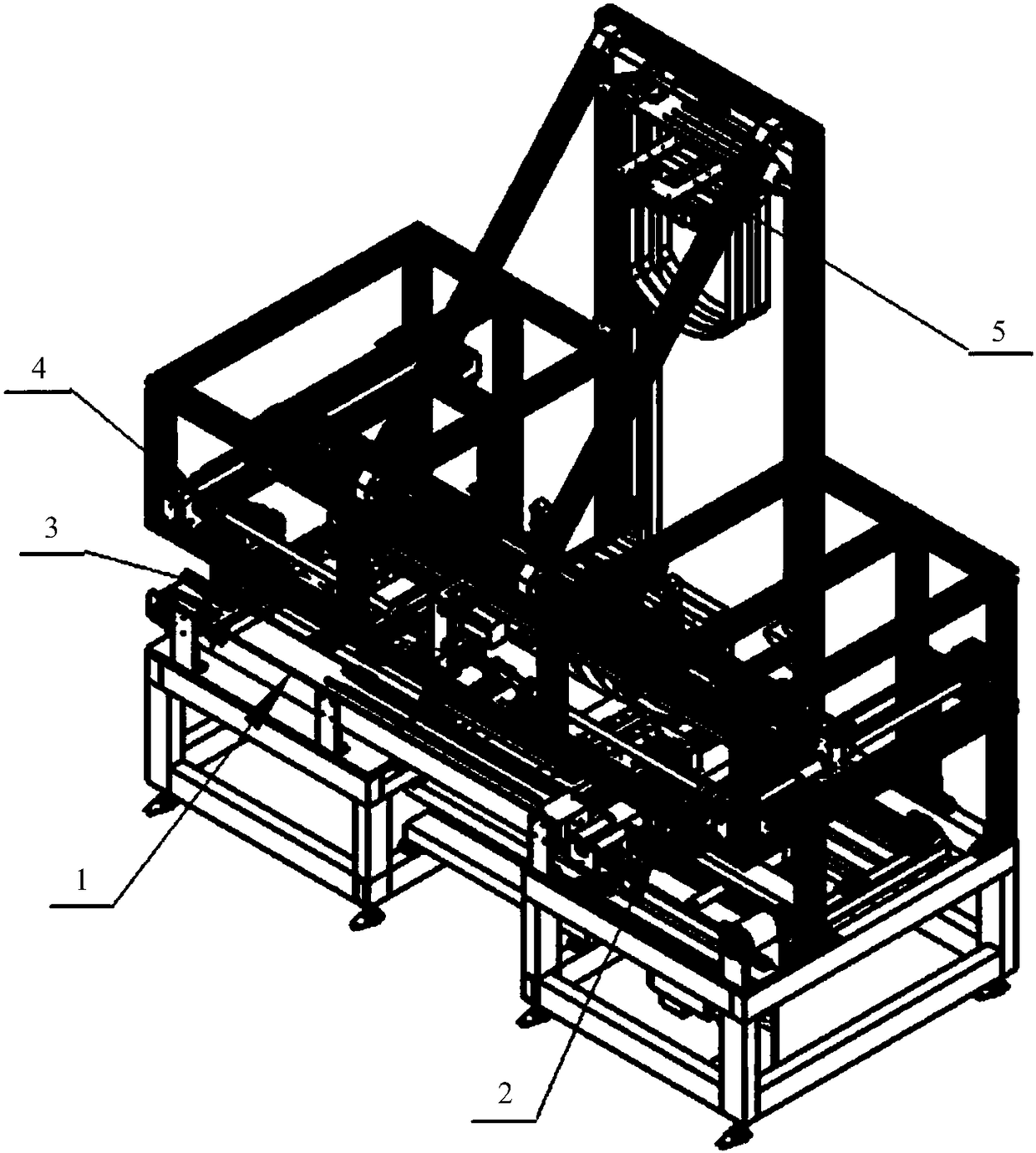
[0047] Please refer to Figure 1 to Figure 8 , an inner tube automatic splicing system, comprising:

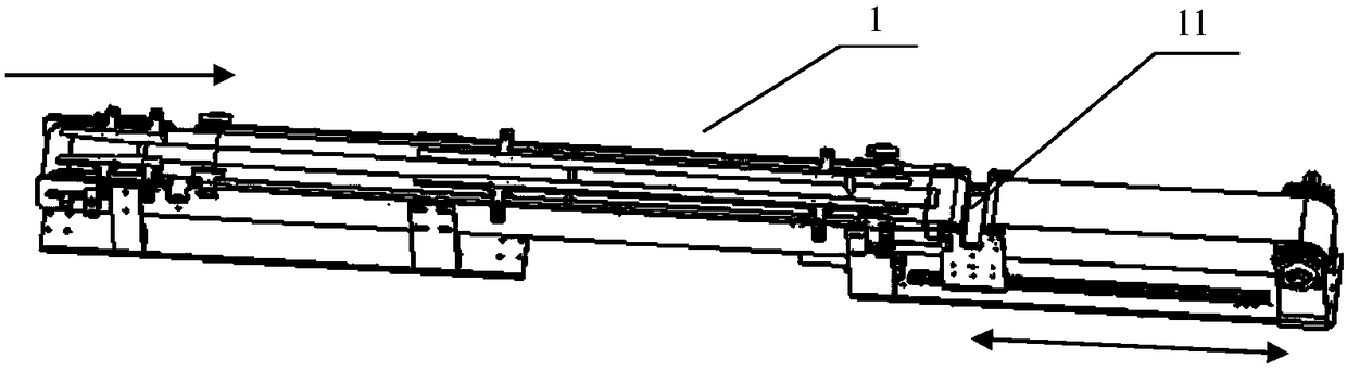
[0048] Incoming conveyor line 1 (see figure 2 ), for delivering the unspliced ​​inner tube to the first position;

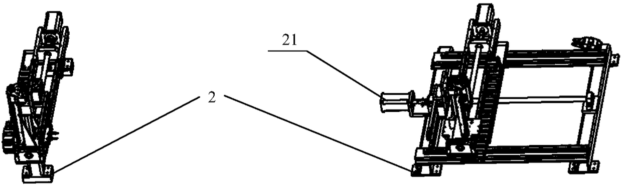
[0049] Reclaiming mechanism 2 (see image 3 ) for clamping the unspliced ​​inner tube from said first position to a second position;

[0050] Feeding turning mechanism 4 (see Figure 4 ), for:

[0051] transporting an unspliced ​​innertube from said second location to a third location;

[0052] Flip the ends of the unspliced ​​inner tube so that the ends face each other;

[0053] Move the two ends of the unspliced ​​inner tube so that they are in zero-distance contact;

[0054] The splicing machine is used to splice the two en...


PUM


Abstract

The invention discloses an automatic inner tube splicing system which comprises an incoming material conveying line, a material taking mechanism, a feeding turnover mechanism, a splicing machine and a discharging mechanism; the incoming material conveying line is used for conveying a non-spliced inner tube to a first position; the material taking mechanism is used for clamping the non-spliced inner tube from the first position to a second position; the feeding turnover mechanism is used for carrying the non-spliced inner tube from the second position to a third position, for turning over the two ends of the non-spliced inner tube to allow the two ends of the non-spliced inner tube to be opposite and for moving the two ends of the non-spliced inner tube to allow the two ends of the non-spliced inner tube to be in contact in zero distance; the splicing machine is used for splicing the two ends, being in contact in zero distance, of the non-spliced inner tube; and the discharging mechanism is used for transferring the spliced inner tube to a fourth position. The automatic inner tube splicing system adopts a full-automatic online operation mode, manual work is replaced by a machine, transferring and accumulation links in the traditional production process are reduced, and the production site is saved.

Description

technical field [0001] The invention relates to the field of inner tube manufacturing, in particular to an inner tube automatic splicing system. Background technique [0002] With the development of society, the labor cost of factories continues to increase, and at the same time, human resources are becoming more scarce. However, inner tube splicing is currently very low in automation in the entire industry and requires a large number of workers to operate. After the inner tube is cut from the injection molding machine, it not only needs to be manually unloaded, but also needs a large number of material accumulation trolleys for transfer. Due to the inconsistency of manual operation, there is a lot of waste to be removed during the splicing process, and the consistency of the inner tube is poor. [0003] The inner tube has its unique properties: soft, slender, and prone to irreversible deformation, so the whole production process needs to be very cautious. However, due to t...

Claims


Application Information

Patent Timeline
Patent Type & Authority Patents(China)
IPC IPC(8): B29C65/00B29C65/78B29L23/24
CPCB29C65/00B29C65/78B29C65/7841B29C65/7858B29L2023/245
Inventor 罗刚葛隽欧阳承明祝林张扬沈德君谢明珍黄澈
Owner ZHEJIANG GUOZI ROBOT TECH
Why Eureka
Try Eureka