Damping device used for large device

A shock absorbing device and large-scale equipment technology, applied in the direction of non-rotational vibration suppression, etc., can solve problems such as deformation, and achieve good buffering effect, good shock resistance, and good deformation prevention effects

Active Publication Date: 2016-12-14
LIANNUOOU MACHINERY TECHOLOGY JIANGSU CO LTD
View PDF6 Cites 1 Cited by
  • Summary
  • Abstract
  • Description
  • Claims
  • Application Information

AI Technical Summary

Problems solved by technology

Using multiple springs, the unbalanced force caused by various factors is decomposed several times, thus solving the problems of earthquake resistance and deformation

Method used


Image

  • Damping device used for large device
  • Damping device used for large device
  • Damping device used for large device

Examples


Embodiment 1

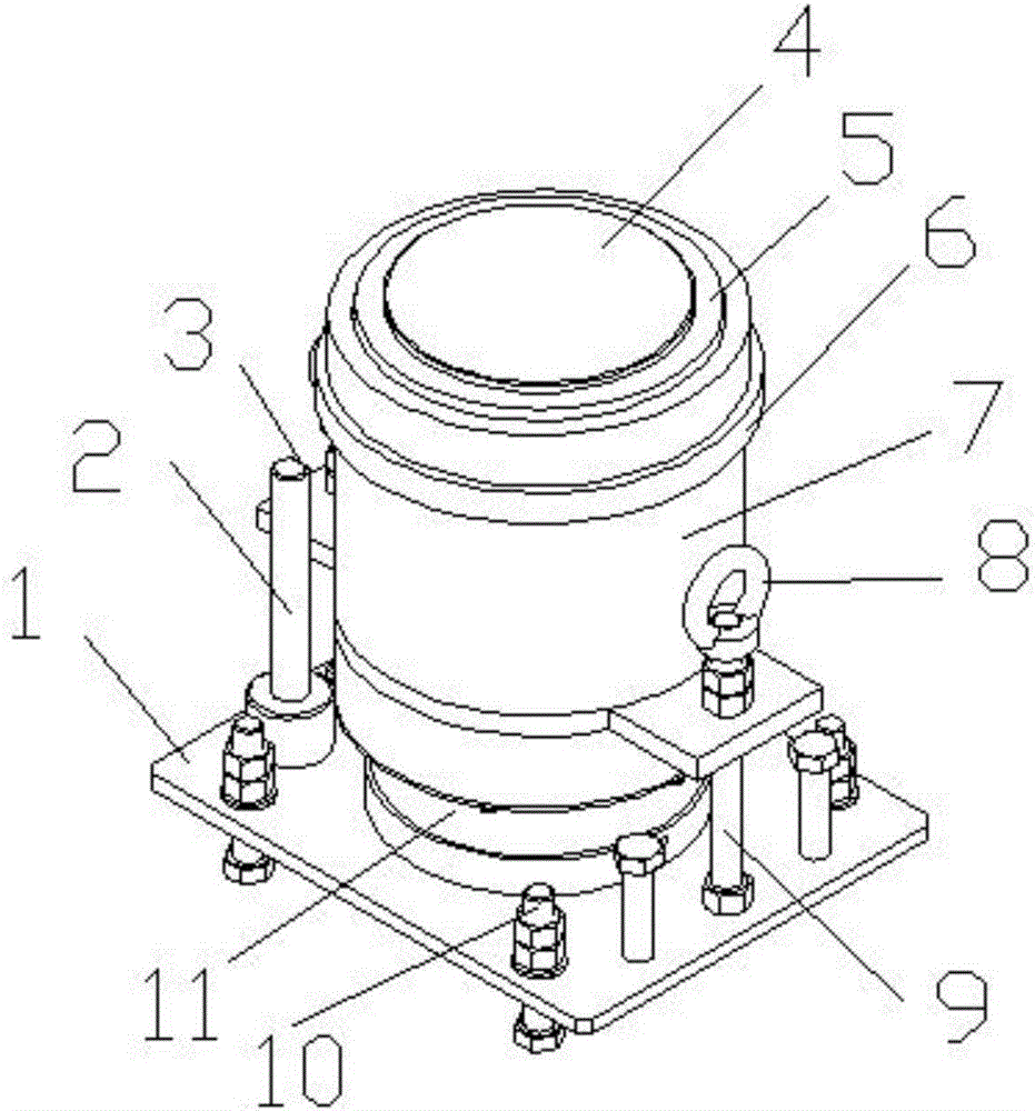
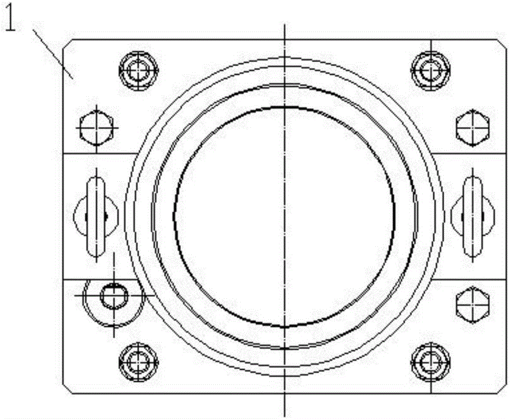
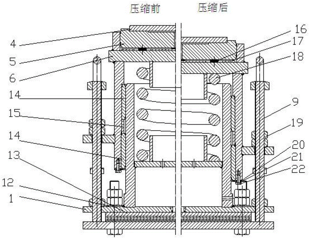
[0019] Embodiment one: if Figures 1 to 3 As shown, the present invention comprises a spring box body, the bottom of the spring box body is provided with a spring box base 1, the upper surface of the spring box base 1 is provided with studs 9 and ring nuts 198, and the four corners of the spring box base 1 are all provided with The second bolt 10, the top of the spring box base 1 is provided with a measuring piece 2 and an inner cylinder wall 11, the outer cylinder wall 11 is covered with an outer cylinder wall 7, and the two sides of the outer cylinder wall 7 are fixed by studs 9 and nuts 19, and the outer cylinder The top of the wall 7 is provided with a spring box top wall, the top of the spring box 6 is provided with a twist cover 5, the twist cover 5 is provided with a slide plate 4, and a slip ring 14 is provided between the inner cylinder wall 11 and the outer cylinder wall 7. The middle part of the slip ring 14 is provided with a guide ring 15, and the inside of the sp...

Embodiment 2

[0021] Embodiment 2: The present invention comprises a spring box body, a spring box base 1 is arranged at the bottom of the spring box body, studs 9 and ring nuts 198 are arranged on the upper surfaces of both sides of the spring box base 1, and four corners of the spring box base 1 are provided with There is a second bolt 10, a measuring piece 2 and an inner cylinder wall 11 are arranged above the spring box base 1, and an outer cylinder wall 7 is set on the outer side of the inner cylinder wall 11, and the two sides of the outer cylinder wall 7 are fixed by studs 9 and nuts 19. The top of the cylinder wall 7 is provided with a spring box top wall, the spring box top 6 is provided with a twist cover 5, the twist cover 5 is provided with a slide plate 4, and a slip ring 14 is provided between the inner cylinder wall 11 and the outer cylinder wall 7, so that The middle part of the slip ring 14 is provided with a guide ring 15, the inside of the spring box body is provided with ...


PUM


Abstract

The invention discloses a damping device used for a large device. The damping device comprises a spring box body, a spring box base is arranged at the bottom of the spring box body, studs and annular nuts are arranged on the upper surfaces of the two sides of the spring box base, the four corners of the spring box base are each provided with a second bolt, a measuring part and an inner cylinder wall are arranged above the spring box base, the outer side of the inner cylinder wall is sleeved with an outer cylinder wall, the two sides of the outer cylinder wall are fixed through the studs and the nuts, a spring box top wall is arranged on the top of the outer cylinder wall, a twisting cover is arranged on the top of a spring box, and a sliding plate is arranged on the twisting cover; a sliding ring is arranged between the inner cylinder wall and the outer cylinder wall, a guide ring is arranged in the middle of the sliding ring, a second spring is arranged in the spring box body, one end of the second spring is connected with the top of the spring box, the other end of the second spring is connected with a baffle arranged on the inner cylinder wall, and a first spring is arranged between the top of the spring box and the twisting cover. The damping device has the beneficial effects of being capable of keeping balance, not prone to deforming, and capable of keeping stable during strong vibration.

Description

technical field [0001] The invention relates to the technical field of shock absorbing devices, in particular to a shock absorbing device for large equipment. Background technique [0002] The large-scale equipment in the prior art can only play a supporting and stabilizing role, but cannot effectively resist earthquakes and alleviate deformation. When the equipment is subject to vibration, unbalance, thermal expansion and contraction, etc., the equipment may not be able to withstand it, resulting in cracking, damage, and failure to use normally. Contents of the invention [0003] Purpose of the invention: In order to overcome the deficiencies in the prior art, the present invention provides a shock-absorbing device for large-scale equipment that can maintain balance, is not easily deformed, and can maintain stability when subjected to strong vibrations. [0004] Technical solution: In order to solve the above technical problems, the present invention provides a shock abs...

Claims


Application Information

Patent Timeline
Patent Type & Authority Applications(China)
IPC IPC(8): F16F15/04
CPCF16F15/04
Inventor 朱昌龙
Owner LIANNUOOU MACHINERY TECHOLOGY JIANGSU CO LTD
Why Eureka
Try Eureka