Assembly type composite wall structure and assembly method thereof

A composite wall and prefabricated technology, which is applied in the direction of walls, building components, building structures, etc., can solve the problems of poor earthquake resistance, easy deformation, falling off, etc., and achieve simple on-site construction, high stability of the overall structure, and convenient installation Effect

Inactive Publication Date: 2021-01-01
SOUTHWEAT UNIV OF SCI & TECH
View PDF5 Cites 0 Cited by
  • Summary
  • Abstract
  • Description
  • Claims
  • Application Information

AI Technical Summary

Problems solved by technology

But at the same time, prefabricated buildings are also prone to many problems such as loose connection and assembly, easy deformation, cracks, poor thermal insulation and ventilation, and poor earthquake resistance.

Method used


Image

  • Assembly type composite wall structure and assembly method thereof
  • Assembly type composite wall structure and assembly method thereof
  • Assembly type composite wall structure and assembly method thereof

Examples


Embodiment 1

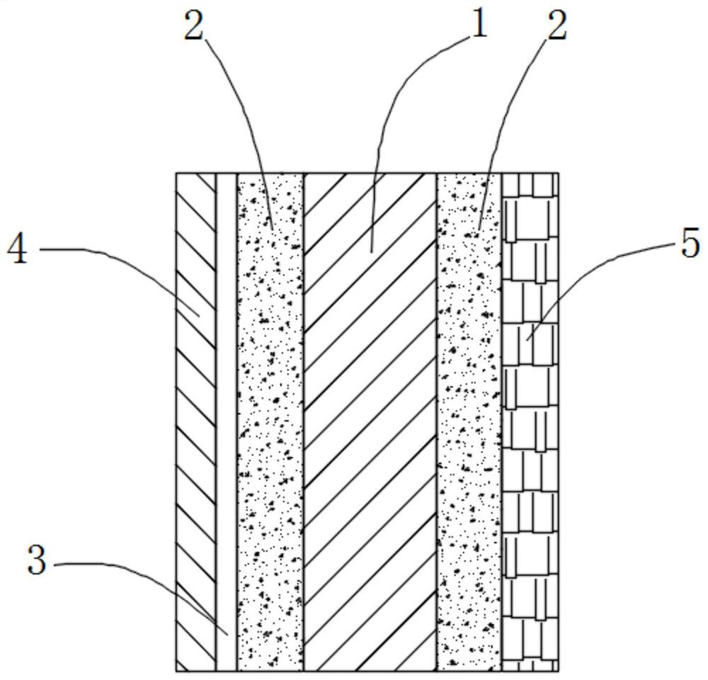
[0033] Such as Figure 1~3 As shown, the present embodiment provides a structural schematic diagram of a prefabricated composite wall structure, including a main beam 1, an insulation layer 2 is provided on both sides of the main beam 1, and the insulation layer 2 is made of mortar queen masterbatch and base material according to the quality The ratio is 5:100, and the base material is composed by weight: 20 parts of fly ash, 50 parts of stone powder, 15 parts of talcum powder, 3 parts of calcium powder, 10 parts of laterite powder, and 5 parts of fine sand. The thermal insulation layer of this embodiment can not only increase the thermal insulation performance of the whole wall, but also increase the structural strength of the thermal insulation layer. However, the existing wall structure only has one layer of insulation layer, and the material of the insulation layer generally adopts insulation material boards, such as perlite insulation boards and polyurethane insulation bo...

Embodiment 2

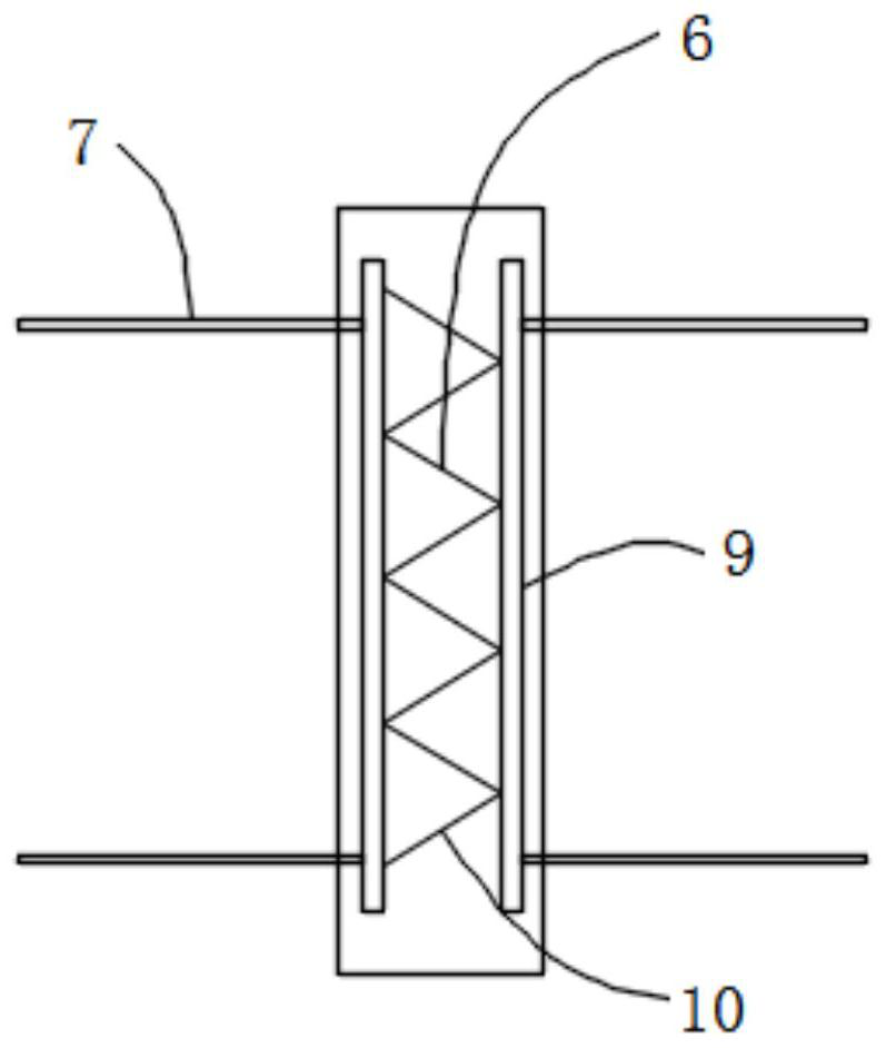
[0038] Such as Figure 1-5As shown, this embodiment provides a prefabricated composite wall structure, and the difference from Embodiment 1 is that: the main beam 1 is also provided with embedded parts 11, and the embedded parts 11 include two vertical main steel bars 9 respectively. The welded steel bar cover 12, the steel bar cover 12 is sleeved with a balance bar 13, and the two ends of the balance bar 13 are fixedly connected to the positioning block 14. In the present embodiment, the balance bar 13 and the positioning block 14 are an integral structure, and the positioning block 14 The quantity is 8, and 8 positioning blocks 14 are respectively 4 / 4 fixed on the upper and lower sides end faces close to the main beam 1, and the fixing blocks are iron blocks or steel blocks. In other embodiments, the balance rib and the positioning block may also be connected by hinges, welding and the like. Regardless of whether the seismic energy is transmitted from the left and right sid...

Embodiment 3

[0040] This embodiment provides an assembled composite wall structure. The difference from Embodiment 2 is that the insulation layer is prepared by mixing the mortar queen mother material and the base material at a mass ratio of 2:100, wherein the base material is prepared in parts by weight The composition includes: 35 parts of fly ash, 100 parts of stone powder, 8 parts of talc powder, 1 part of calcium powder, 6 parts of laterite powder, 15 parts of fine sand, 5 parts of expanded perlite, and 3 parts of silanized polypropylene fiber.


PUM

PropertyMeasurementUnit
thicknessaaaaaaaaaa

Abstract

The invention relates to an assembly type composite wall structure and an assembly method thereof. The wall structure comprises a main beam, heat preservation layers are arranged on the two sides of the main beam, a steel plate is arranged on one side of the heat preservation layer on one side, and a calcium silicate plate is arranged on the other side of the steel plate; a waterproof layer is arranged on one side of the heat preservation layer on the other side; and a steel reinforcement framework is arranged in the main beam, and the steel reinforcement framework penetrates through the heatpreservation layers through side tie bars connected with the two sides of the steel reinforcement framework to be connected with the steel plate and the waterproof layer. The assembly method comprisesthe following steps that a plurality of main beam steel reinforcement frameworks and side tie bars are manufactured and then put into a mold to be poured with concrete to form a main beam blank, andthe main beam blank is cut to form a main beam and transported to the site to wait for assembling; the two sides of the main beam are coated to form the heat preservation layers; the steel plate is assembled outside the heat preservation layer on one side, the steel plate is welded with the side tie bars, and then the calcium silicate plate is assembled on the other side of the steel plate; and the waterproof layer is formed outside the heat preservation layer on the other side.

Description

technical field [0001] The invention relates to the technical field of wall construction, in particular to an assembled composite wall structure and an assembly method thereof. Background technique [0002] With the development of modern industrial technology, building houses can be manufactured in batches and in sets like machine production. Just transport the prefabricated building components to the construction site and assemble them. Prefabricated buildings mainly include prefabricated concrete structures, steel structures, modern wooden structures, etc., because of the use of standardized design, factory production, assembly construction, information management, and intelligent applications, they are representatives of modern industrial production methods. Prefabricated buildings do greatly reduce the difficulty and intensity of on-site operations, save construction time and improve construction efficiency. But at the same time, prefabricated buildings are also prone ...

Claims


Application Information

Patent Timeline
Patent Type & Authority Applications(China)
IPC IPC(8): E04B2/00E04B1/76E04B1/66E04B1/41E04G21/14B28B1/14B28B23/02C04B28/00C04B111/27
CPCB28B1/14B28B23/02C04B28/00C04B2111/00612C04B2111/27E04B1/41E04B1/66E04B1/76E04B2/00E04G21/14C04B18/08C04B14/02C04B14/042C04B14/28C04B14/361C04B14/06C04B14/185C04B16/0633C04B2103/0068C04B24/383C04B2103/0045C04B2103/302Y02A30/244
Inventor 杨东升姚勇褚云朋张兆强邓勇军
Owner SOUTHWEAT UNIV OF SCI & TECH
Why Eureka
Try Eureka