[0024] The present invention will be further described in detail below with reference to the drawings and specific embodiments.
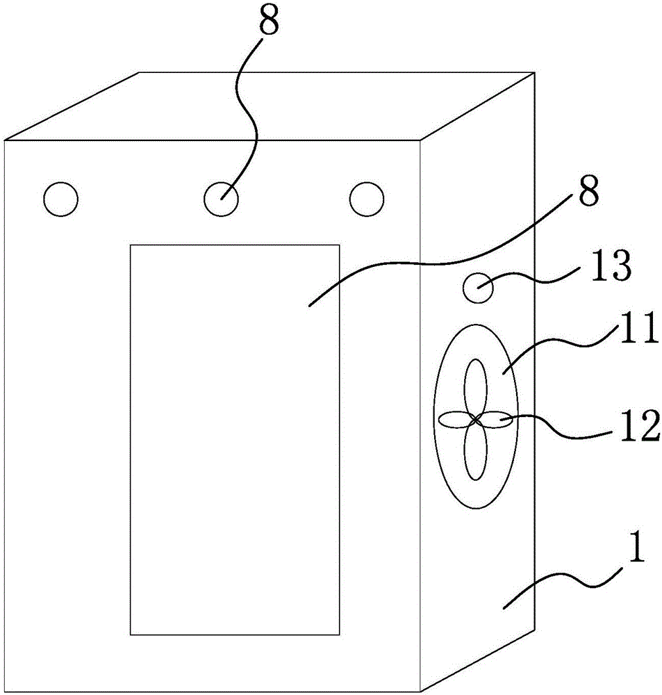
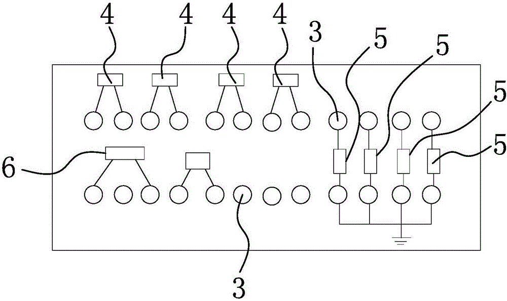
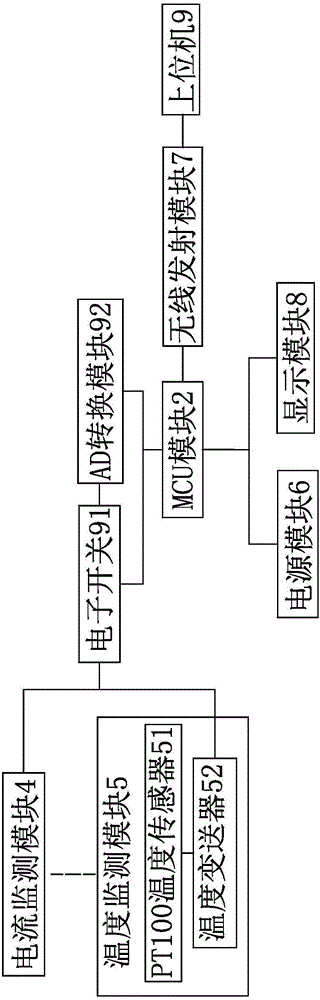
[0025] Such as Figure 1-3 As shown, the smart electricity safety monitoring system includes a number of current monitoring modules 4 and a number of temperature monitoring modules 5 respectively connected to the electrical appliances to be monitored. The current monitoring module 4 and the temperature monitoring module 5 respectively pass through an electronic switch 91 and an AD conversion module 92 The AD conversion module 92 and the electronic switch 91 are respectively connected to the MCU module 2. The MCU module 2 is connected to the power module 6, and the MCU module 2 is connected to the host computer 9 through the wireless communication module 7, and the MCU module 2 and the host computer 9 are bidirectional For data transmission, the wireless communication module 7 here can be a GPRS module, and the temperature monitoring module 5 here can include a PT100 temperature sensor 51. The PT100 temperature sensor 51 is connected to the electronic switch 91 through a temperature transmitter 52; the current monitoring module 4 is a current true For the effective value converter, the monitoring housing 1 here is provided with a display module 8 connected to the MCU module 2; the display module 8 is a display screen and/or indicator lamp provided on the monitoring housing 1.
[0026] Specifically, the MCU module 2 and the wireless communication module 7 in this embodiment are both arranged in the inner cavity of a monitoring housing 1. The monitoring housing 1 is provided with a number of connection terminals 3 respectively connected to the MCU module 2. A number of connection terminals At least eight terminals 3 of 3 are connected to a number of current monitoring modules 4, at least eight terminals 3 of a number of terminals 3 are connected to a number of temperature monitoring modules 5, and at least two terminals 3 of a number of terminals 3 are respectively connected to a power module 6 is connected, the specific wiring method is: 1-24 terminal 3 is provided on the monitoring housing 1, among which, between 1-2 terminal 3, between 3-4 terminal 3, and between 5-6 terminal 3 The current monitoring module 4 is connected between the 7-8 terminal 3 and between the 9 terminal 3 and 21 terminal 3, between 10 terminal 3 and 22 terminal 3, 11 terminal 3 and 23 terminal Temperature monitoring module 5 is connected between terminal 3 and between terminal 12 and terminal 3 and terminal 24 respectively. Power module 6 is connected between terminal 13 and terminal 15 and power module 6 is connected between terminal 13 and terminal 3 and power module 6. The positive pole is connected, the 15 terminal 3 is connected to the negative pole of the power module 6, and the 11 terminal 3 and the 23 terminal 3 are the alarm relay output interfaces.
[0027] Further, a ventilation window 11 is provided on one side of the monitoring housing 1 here, and a fan 12 connected to the inner cavity of the monitoring housing 1 and connected to the MCU module 2 is provided in the ventilation window 11, and the MCU module 2 is connected to the monitor When the casing 1 is in the vertical state, the fan 12 can be connected with the MCU module 2 and when the monitoring casing 1 is not in the vertical state, the mercury switch can block the fan 12 and the MCU module 2, and the mercury switch is in the vertical direction It is set in the monitoring housing 1, and one pole of the mercury switch is connected to the power supply module 6, and the other pole is connected to the MCU module 2. The MCU module 2 is also connected to the fan status display lamp 13 provided on the monitoring housing 1, namely During actual installation, the monitoring housing 1 needs to be installed vertically to enable the mercury switch to connect the fan 12 with the MCU module 2, and the fan status indicator 13 is lit to indicate that the mounting position of the monitoring housing 1 is accurate.
[0028] This smart electricity safety monitoring method includes: A. Install each monitoring module: connect each current monitoring module 4 and temperature monitoring module 5 to the electrical appliances to be monitored, and set a fixed IP to connect MCU module 2 to host computer 9 and bidirectional Data transmission; B. Monitoring module data collection: the current monitoring module 4 converts the AC current connected to the current monitoring module 4 into a DC voltage, and the temperature monitoring module 5 converts the collected temperature information into voltage, and sends it to the electronic switch 91 The AD conversion module 92 performs sampling, and the MCU module 2 calculates the corresponding analog value, and then sends it to the fixed IP of the host computer 9 through the wireless communication module 7, so that the host computer 9 can view the values of various parameters on site in real time. Collection, real-time monitoring of the temperature and power of each appliance to be monitored on site.
[0029] Further, the MCU module 2 and the wireless communication module 7 in this embodiment are both arranged in the inner cavity of a monitoring housing 1. The monitoring housing 1 is provided with a plurality of wiring terminals 3 respectively connected to the MCU module 2, and a plurality of wiring terminals At least eight terminals 3 in 3 are connected to a number of temperature monitoring modules 5, and at least two of the terminals 3 are connected to a power supply module 6 respectively; the temperature monitoring module 5 includes a PT100 temperature sensor 51, and a PT100 temperature sensor 51 passes temperature The transmitter 52 is connected to the electronic switch 91; the current monitoring module 4 is a current true effective value converter; the wireless communication module 7 is a GPRS module; the monitoring housing 1 is provided with a display module 8 connected to the MCU module 2; a display module 8 It is a display screen and/or indicator lamp arranged on the monitoring housing 1.
[0030] Here, one side of the monitoring housing 1 is provided with a ventilation window 11, and the ventilation window 11 is provided with a fan 12 communicating with the inner cavity of the monitoring housing 1 and connected to the MCU module 2. The MCU module 2 is connected to the monitoring housing 1. A mercury switch that enables the fan 12 to communicate with the MCU module 2 when it is in the vertical state, and can block the fan 12 and the MCU module 2 when the monitoring housing 1 is not in the vertical state, and the mercury switch is set in the monitor in the vertical direction One pole of the mercury switch is connected to the power supply module 6 and the other pole is connected to the MCU module 2. The MCU module 2 is also connected to the fan status display lamp 13 arranged on the monitoring housing 1.
[0031] The specific embodiments described herein are merely examples to illustrate the spirit of the present invention. Those skilled in the art to which the present invention pertains can make various modifications or additions to the specific embodiments described or use similar alternatives, but they will not deviate from the spirit of the present invention or exceed the definition of the appended claims. Range.
[0032] Although this article uses more monitoring housing 1, ventilation window 11, fan 12, fan status indicator 13, MCU module 2, terminal block 3, current monitoring module 4, temperature monitoring module 5, PT100 temperature sensor 51, temperature change Terms such as transmitter 52, power module 6, wireless communication module 7, display module 8, host computer 9, electronic switch 91, AD conversion module 92, etc., but the possibility of using other terms is not excluded. These terms are used only to describe and explain the essence of the present invention more conveniently; to interpret them as any additional limitation is contrary to the spirit of the present invention.