Power transmission line indicating device with insulation structure

A technology of transmission lines and indicating devices, which is applied in the direction of display devices, signs, instruments, etc., can solve the problems of high production costs, achieve low production costs, realize live installation, and easy installation

Inactive Publication Date: 2016-12-14
STATE GRID CORP OF CHINA +2
View PDF13 Cites 0 Cited by
  • Summary
  • Abstract
  • Description
  • Claims
  • Application Information

AI Technical Summary

Problems solved by technology

Chinese patent application number: 2016108239344 proposes a "transmission line indicator ball" to solve the above problems, but this "transmission line indicator ball" can only be installed on a power failure or dead wire
The above two kinds of indicator balls have metal parts inside, and the production cost is high

Method used


Image

  • Power transmission line indicating device with insulation structure
  • Power transmission line indicating device with insulation structure
  • Power transmission line indicating device with insulation structure

Examples


Embodiment 1

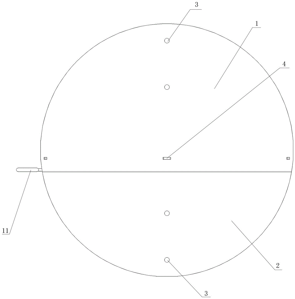
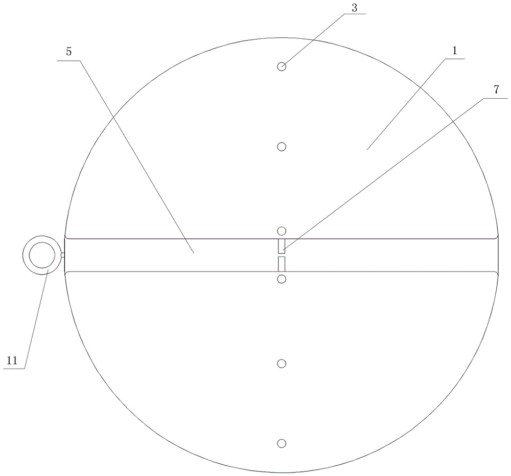
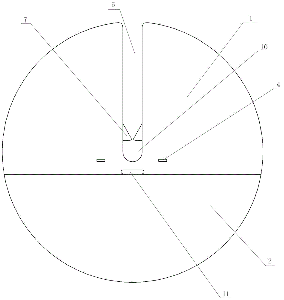
[0020] Figure 1 to Figure 7 It is a schematic diagram of a power transmission line indicating device with an insulating structure in Example 1 of the present invention; a power transmission line indicating device with an insulating structure in the present invention includes an upper hemisphere 1 and a lower hemisphere 2, and the spherical shell of the upper hemisphere 1 has water leakage holes 3. Buckle hole 4, U-shaped groove 5; leak hole 3, buckle hook 6, buckle extension section 8 are arranged on the spherical shell of the lower hemisphere 2; buckle hook 6 is arranged on the buckle extension section 8, and upper hemisphere 1 It is fastened together with the lower hemisphere 2 through the button hole 4 and the buckle hook 6 to form a spherical body, which is characterized in that: the U-shaped groove 5 on the spherical shell of the upper hemisphere 1 has a stopper 7, and the ball of the lower hemisphere 2 An operating rod connecting hole 9 is arranged on the shell, and a s...

Embodiment 2

[0023] Figure 8 It is a schematic diagram of a power transmission line indicating device with an insulating structure according to Embodiment 2 of the present invention; the power transmission line indicating device with an insulating structure according to Embodiment 1 is characterized in that: the U-shaped groove 5 on the spherical shell of the upper hemisphere 1 7 is more than 2; present embodiment 2 is 6, to guarantee that this device is firmly connected with the transmission line.

[0024] The material of the housing of the transmission line indicating device of the insulation structure may be plastic, resin, rubber and the like.

[0025] The color of the transmission line indicating device of the insulation structure can be bright colors such as yellow, orange yellow, bright red, also can be coated with reflective color.

[0026] The upper hemisphere and the lower hemisphere of the power transmission line indicating device of the insulating structure can be glued toget...


PUM


Abstract

A power transmission line indicating device with an insulation structure comprises an upper semi-sphere and a lower semi-sphere, wherein a water leakage hole, a buckling hole and a U-shaped groove are formed in a sphere shell of the upper semi-sphere; a water leakage hole, a buckling hook and a buckling extension section are disposed on a sphere shell of the lower semi-sphere; and the buckling hook is disposed on the buckling extension section, and the upper semi-sphere and the lower semi-sphere are buckled together by the buckling hole and the buckling hook to form a spherical body. The device is characterized in that anti-separation teeth are disposed in the U-shaped groove of the upper semi-sphere; an operation rod connecting hole is formed in the sphere shell of the lower semi-sphere; and screw threads are formed in the operation rod connecting hole. The device has the beneficial effects that the power transmission line indicating device with the insulation structure has the low production cost; electrified installation can be achieved; the installation is convenient; and movable objects such as flying objects are prevented from running into or touching a power transmission line and causing accidents.

Description

technical field [0001] The invention relates to a prompting device for a power transmission line, in particular to a power transmission line indicating device with an insulating structure. Background technique [0002] Power transmission lines are spread all over the world. Because the lines are relatively thin, it is difficult to see flying objects at long distances, such as airplanes, gliders, skydiving, flying with wingsuits, drones, agricultural aircraft, helicopter lifting, crane operations, birds It is very likely that flying or the like will bump into or touch the power transmission line. Such accidents occur from time to time, causing casualties and heavy property losses. In some places, signs are hung on the road, and when looking along the direction of the line, the sign is not visible. Chinese patent application number: 2016108239344 proposes a "power transmission line indicator ball" to solve the above problems, but this "power transmission line indicator ball" ...

Claims


Application Information

Patent Timeline
IPC IPC(8): G09F7/18
CPCG09F7/18G09F2007/1839
Inventor 赵树海赵清海
Owner STATE GRID CORP OF CHINA
Why Eureka
Try Eureka