
endoscope

An endoscope and optical fiber technology, applied in the field of endoscope, can solve the problems of thickening of the outer diameter of the insertion part, adverse effects on optical performance, etc., and achieve the effect of preventing misassembly, reliable and easy optical performance

Active Publication Date: 2018-05-01
OLYMPUS CORP
View PDF11 Cites 0 Cited by
  • Summary
  • Abstract
  • Description
  • Claims
  • Application Information

AI Technical Summary

Problems solved by technology

Therefore, the optical fiber surrounding the observation optical system may cause the outer diameter of the insertion part to become thicker.
In addition, since the tip of the optical fiber is brought into contact with the prevention part, part of the illumination light irradiated from the tip of the fiber directly enters the tip without passing through the lens system, which may adversely affect the optical performance.

Method used


Image

  • endoscope
  • endoscope
  • endoscope

Examples


Embodiment Construction

[0027] Hereinafter, embodiments of the present invention will be described with reference to the drawings.

[0028] In addition, in each of the drawings used in the following description, each component has a size that can be recognized on the drawing, so the scale is different for each component. Furthermore, the present invention is not limited to the number of constituent elements, the shape of the constituent elements, the size ratio of the constituent elements, and the relative positional relationship of the constituent elements described in these drawings.

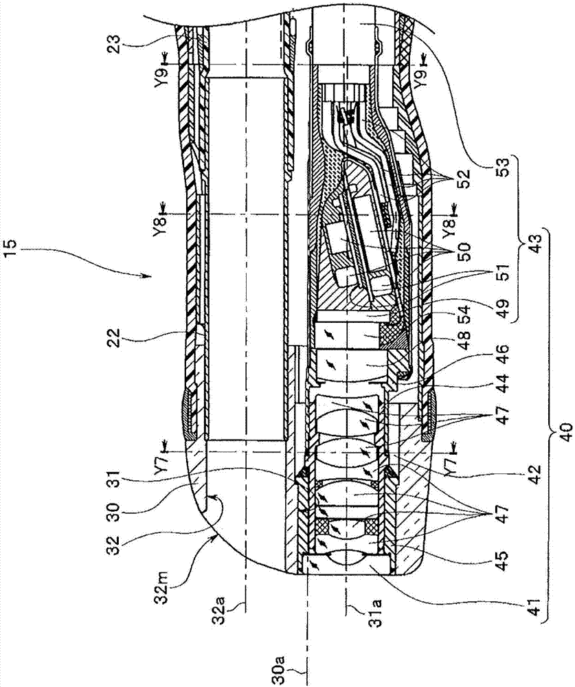
[0029] figure 1 The illustrated endoscope 10 is, for example, a ureteroscope, and is mainly composed of an insertion unit 11 , an operation unit 12 , and an eyepiece unit 13 . The eyepiece portion 13 is provided on the base end side of the operation portion 12 .

[0030] Reference numeral 14 is a universal cord, and the connector 14c of the universal cord 14 is detachable with respect to the light guide connection ...


PUM


Abstract

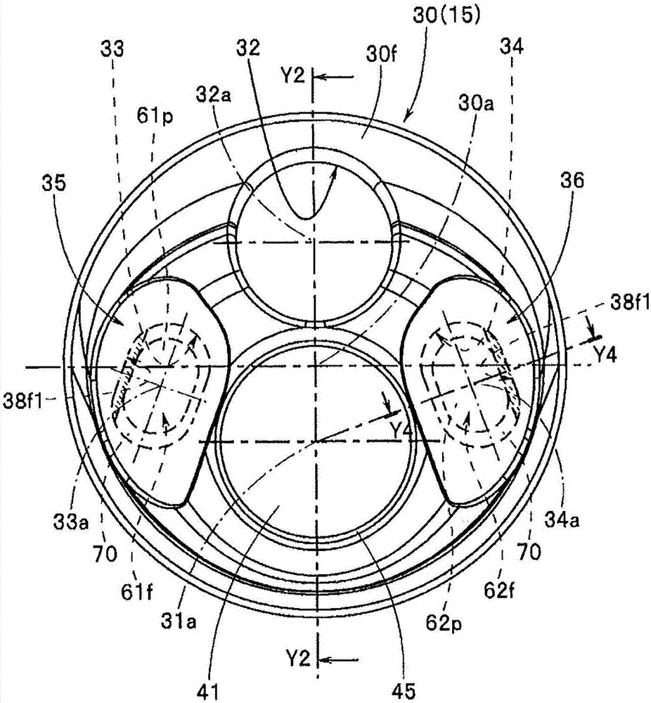
The endoscope (10) has: a first fiber (61) of an optical fiber (60) provided at the front end with an exit angle formed at an angle smaller than 90 degrees relative to the longitudinal axis (61a). A first plane (61f) of illumination light; a tube (70) having a through-hole (71) in which the tip portion (61p) of the first fiber (61) is fixedly set, the tube ( 70) The front end surface (73) has a first surface (73a) that can be the same plane as the first plane (61f) and a second surface (73b) that is a plane perpendicular to the central axis (71a) of the through hole (71). ); and the front end structural part (30), which is formed with the blind hole (34) at the end of the front end side of the configuration pipe (70), and the second end of the pipe (70) is provided on the bottom surface side of the blind hole (34). A contact surface (38f2) on which at least a part of the surface (73b) contacts, and a concave part (37) located on the front end side of the contact surface (38f2) and constituting an illumination lens system for obtaining a predetermined light distribution .

Description

technical field [0001] The present invention relates to an endoscope configured such that an end portion having an output end surface of an optical fiber is fixedly installed in a concave portion corresponding to an illumination window portion formed of a transparent resin member. Background technique [0002] Endoscopes are widely used in the medical and industrial fields. An object of diagnosis or an object of observation by an endoscope is a living body, an inside of a mechanical device, or the like. Therefore, in an endoscope apparatus, a light source for illuminating a diagnosis object or an observation object is required. [0003] A general endoscope device includes an endoscope and a light source device as an external device of the endoscope. The light source device incorporates a light emitting source such as a lamp for emitting illumination light or a light emitting element. [0004] The illumination light emitted from the light emitting source is transmitted thr...

Claims


Application Information

Patent Timeline
Patent Type & Authority Patents(China)
IPC IPC(8): A61B1/00G02B23/26
CPCG02B23/243G02B23/2469A61B1/00071A61B1/00096A61B1/0011A61B1/00135A61B1/307A61B1/06A61B1/0607A61B1/00167A61B1/07A61B1/00057A61B1/00105A61B1/00128A61B1/00142A61B1/00195A61B1/018
Inventor 金子浩之
Owner OLYMPUS CORP
Learn More