X-ray CT device and processing device
A technology of X-ray and CT images, applied in the field of iterative reconstruction technology, can solve problems such as increased calculation amount and optimization of a large number of parameters
- Summary
- Abstract
- Description
- Claims
- Application Information
AI Technical Summary
Problems solved by technology
Method used
Image
Examples
Embodiment 1
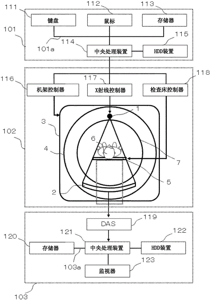
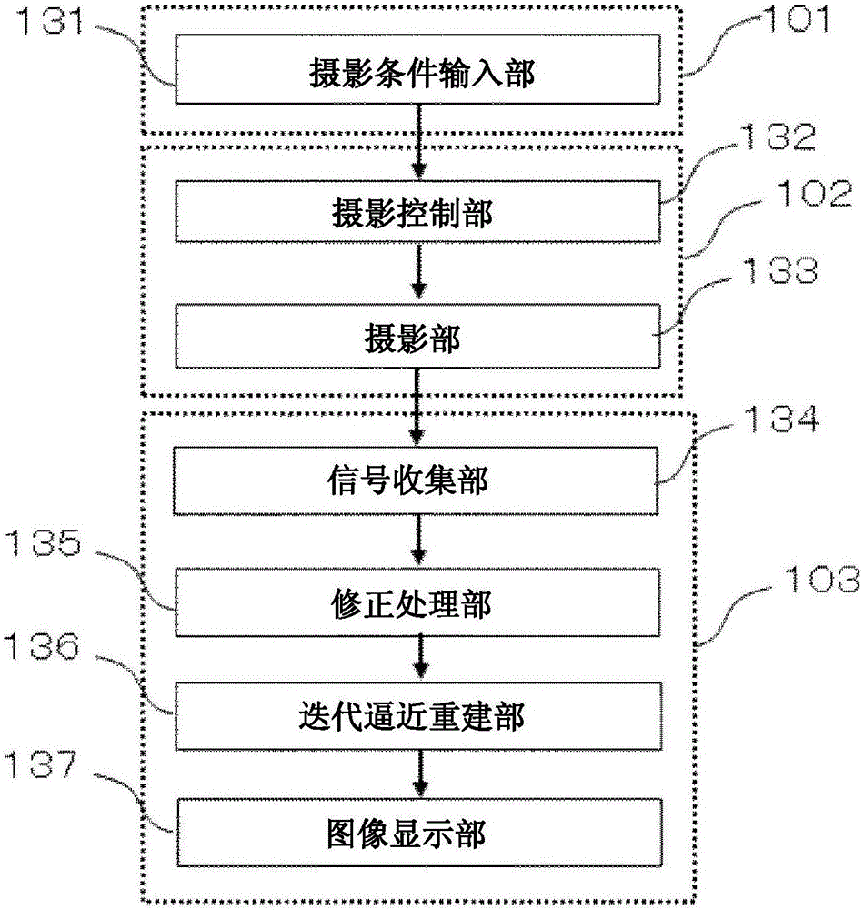
[0055] figure 1 A diagram showing a hardware configuration of an X-ray CT apparatus according to Embodiment 1, figure 2 A functional block diagram showing the functions of the X-ray CT apparatus of the first embodiment is shown. This embodiment is an embodiment of such an X-ray CT apparatus, which includes: an imaging unit 102, which includes an X-ray generating unit 1 that generates X-rays, and a unit that detects X-rays transmitted from an object to obtain measurement projection data. The X-ray detection unit 2, and a mechanism that is equipped with the X-ray generation unit and the X-ray detection unit and rotates around the subject; and the image generation unit 103 includes an iterative approximation reconstruction unit 136 based on The CT image is generated from the measured projection data from the imaging unit, and the CT image is iteratively corrected so that the difference between the calculated projection data and the measured projection data obtained by forward p...
Embodiment 2
[0152] Next, the X-ray CT apparatus of Example 2 will be described.
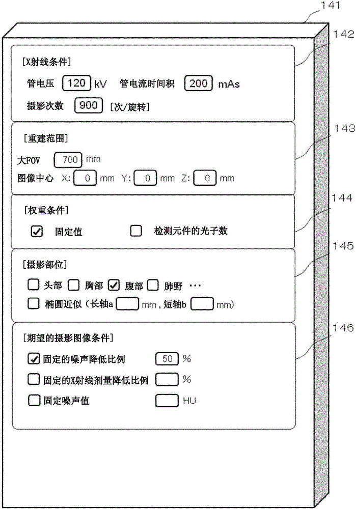
[0153] In the first embodiment described above, in the case where the weight set to a fixed value in the weight setting area 144 is adopted, the reference parameter β b , base weight W b And the weight image W of each position I (j) Calculation parameter β image β I (j) Structure. On the other hand, in Example 2, when the weight setting area 144 is set to the number of photons of the detection element, the reference parameter β calculated with a weight of a fixed value is used. b and base weight W b , and the weight image W of each position calculated by the number of photons of the detection element I (j), to calculate the parameter β image β I (j). The configuration of the X-ray CT apparatus according to the second embodiment will be described below focusing on configurations different from those of the X-ray CT apparatus according to the first embodiment.
[0154] Figure 11 Shown is a weighted i...
Embodiment 3
[0160] Next, the X-ray CT apparatus of Example 3 will be described. In the above-mentioned first embodiment, when the weight set to a fixed value in the weight setting area 144 is used, the reference weight W set at the rotation center at the reference position is used. b , benchmark parameter β b And the weight image W of each position I (j) to calculate the parameter β image β I (j) Structure. In Embodiment 3, not only the center of rotation but a plurality of reference weights W are used b , multiple reference parameters β b And the weight image W of each position I (j), to calculate the parameter β image β I (j) Structure. The configuration of the X-ray CT apparatus according to the third embodiment will be described below focusing on configurations different from those of the X-ray CT apparatus according to the first embodiment.
[0161] Figure 14 The left side of shows that in the table calculation unit 170, when using each reference parameter β bIn the CT ima...
PUM
 Abstract
Description
Claims
Application Information
 - R&D
- Intellectual Property
- Life Sciences
- Materials
- Tech Scout
- Unparalleled Data Quality
- Higher Quality Content
- 60% Fewer Hallucinations
Browse by: Latest US Patents, China's latest patents, Technical Efficacy Thesaurus, Application Domain, Technology Topic, Popular Technical Reports.
© 2025 PatSnap. All rights reserved.Legal|Privacy policy|Modern Slavery Act Transparency Statement|Sitemap|About US| Contact US: help@patsnap.com


