Hydraulic system of a transmission with a plurality of pressure regulating valves

A technology of pressure regulation and hydraulic system, applied in the direction of clutches, geared elements, fluid-driven clutches, etc., can solve the problem of spontaneous reduction of pressure rise and achieve the effect of reducing structural space requirements

Active Publication Date: 2016-12-14
ZF FRIEDRICHSHAFEN AG
View PDF7 Cites 2 Cited by
  • Summary
  • Abstract
  • Description
  • Claims
  • Application Information

AI Technical Summary

Problems solved by technology

The spontaneity of the pressure increase is significantly reduced the greater the displacement to be moved by the valve slides in each case

Method used


Image

  • Hydraulic system of a transmission with a plurality of pressure regulating valves
  • Hydraulic system of a transmission with a plurality of pressure regulating valves
  • Hydraulic system of a transmission with a plurality of pressure regulating valves

Examples


Embodiment Construction

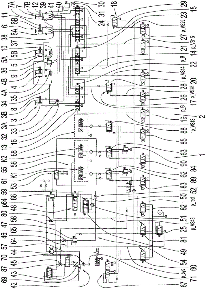
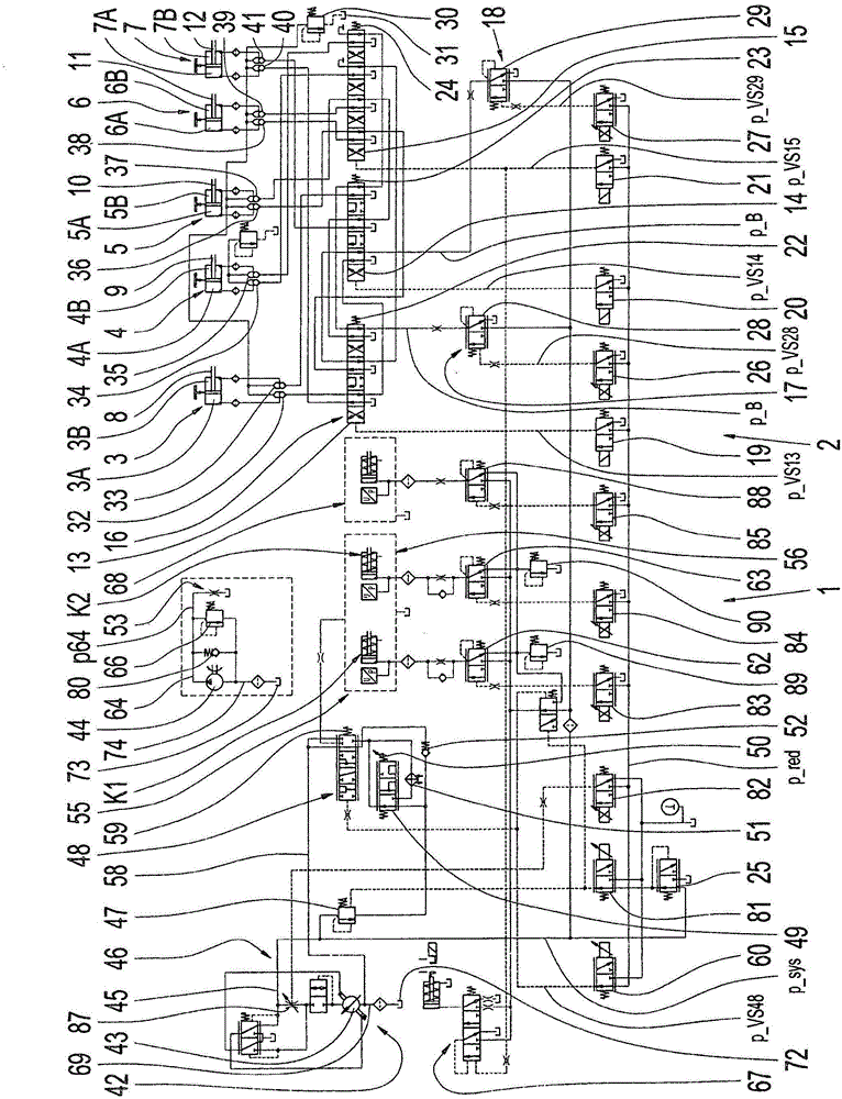
[0042] figure 1 A hydraulic diagram is shown of the hydraulic system 1 or the hydraulic actuation of the transmission 2 , which is currently embodied as a dual clutch transmission, in which nine transmission ratios for forward travel and one transmission ratio for reverse travel can be engaged. The individual gear ratios can be engaged and disengaged via shifting elements 8 to 12 which are movable by means of five hydraulically actuatable piston-cylinder arrangements 3 to 7 , which are presently designed as selector levers. The actuating pressure p_B can be applied in the region of the piston-cylinder arrangements 3 to 7 or in the piston chambers 3A, 3B or 4A via the valve arrangement 16 which currently comprises three pre-controlled control valves 13 to 15 interconnected via respective lines. , 4B or 5A, 5B or 6A, 6B or 7A, 7B area. The control valves 13 to 15 each have a plurality of switching positions for forming the transmission ratios. The actuating pressure p_B is fre...


PUM


Abstract

A hydraulic system (1) for a transmission (2) having a plurality of pressure regulating valves (62 to 29) is described, in the region of which valves, an applied pressure (p_sys) can be adjusted to a pressure level to be set downstream as a function of a total force component engaging at each valve slider depending on the operating state. The total force component appears as a function of a pilot control force component applicable on each valve slider, an actuating force component, and a regulating force component dependent on the pressure level prevailing downstream. The pilot control force component and the actuating force component can each be applied on the valve slider in an equally acting way in the direction of a first end position of the valve slider of a pressure regulating valve (62 to 29), in which position the region upstream of the pressure regulating valve (62 to 29) is connected to the region downstream of the pressure regulating valve (62 to 29) via the pressure regulating valve, whereas the pressure downstream of the pressure regulating valve (62 to 29) can be applied on the valve slider, acting counter to the pilot control force component and the actuating force component, in the direction of a second end position of the valve slider, in which position the region downstream of the pressure regulating valve (62 to 29) is connected to a low pressure region (71).

Description

technical field [0001] The invention relates to a transmission hydraulic system of the type described in more detail in the preamble of claim 1 , comprising a plurality of pressure regulating valves. Background technique [0002] In order to prevent an unloaded operation of the hydraulic lines of the known transmission hydraulic system, a plurality of pressure control valves of the hydraulic system, such as clutch valves or other clutch valves assigned to hang-on clutches, are operatively connected to so-called prefill valves. . Usually a plurality of pressure regulating valves of a plurality of hydraulic actuating devices of a hydraulic system or a transmission share a common prefill valve. A certain minimum pressure is set in the hydraulic line in the region of the prefill valves, with typical values ​​between 0.2 and 0.4 bar. They are generally constructed as spring-loaded seat valves, such as disk valves. The prefill valves themselves can be adjusted to a constant pre...

Claims


Application Information

Patent Timeline
Patent Type & Authority Applications(China)
IPC IPC(8): F16H61/00F16H61/02F16H61/688
CPCF16H61/0021F16H61/0206F16H61/688F16D48/0206F16H61/0031F16D25/14
Inventor R·诺瓦克T·普夫勒格A·霍夫曼M·特瓦尔特
Owner ZF FRIEDRICHSHAFEN AG
Why Eureka
Try Eureka