
Shoe washing machine

A shoe washing machine and chassis technology, applied in the field of shoe washing machines, can solve the problems of wasting water, difficult to clean, tearing, etc., and achieve the effect of saving water resources and convenient fixing

Inactive Publication Date: 2016-12-21
SHAANXI UNIV OF SCI & TECH
View PDF3 Cites 3 Cited by
  • Summary
  • Abstract
  • Description
  • Claims
  • Application Information

AI Technical Summary

Problems solved by technology

[0004] 1. There are no rules for shoe placement
[0005] 2. The brush in the center of the straight cylinder cannot clean the inside of the shoe, and it will cause great damage to the surface of the shoe
[0006] 3. The way of washing shoes is the same as that of the washing machine, stirring back and forth, it is easy to cause problems such as degumming and tearing
[0007] 4. Pour the shoes to be washed into the shoe washing machine and stir them back and forth, which will cause pollution and cross-infection of germs. The more the shoes are washed, the dirtier they will be, and there are safety and health problems.
[0008] 5. During the whole shoe washing process, the shoes are completely soaked in water and stirred back and forth in the water, the shoes are easy to degumming
[0009] 6. The washing mode is almost the same as that of the washing machine, which is a serious waste of water
[0010] 7. A lot of detergent is needed in the process, the shoes are difficult to clear, and it pollutes the water quality, which is not environmentally friendly
[0011] 8. There is no disinfection function, and it is difficult to clean the inside of the cylinder after washing the shoes
[0012] 9. Use the method of drying to remove water, the effect is not good and it will damage the shoes

Method used


Image

  • Shoe washing machine
  • Shoe washing machine
  • Shoe washing machine

Examples


Embodiment Construction

[0033] The implementation of the present invention will be described in detail below in conjunction with the drawings and examples.

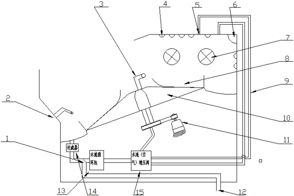
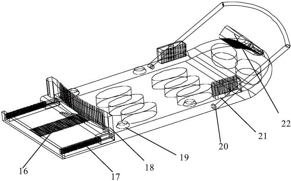
[0034] Such as figure 1 Shown, a kind of shoe-washing machine comprises a chassis, in which there are inclined turntables 10, disinfection lamps 6, dryers 7 and net pockets for collecting impurities, etc., and a machine cover and a control device are arranged outside the casing. Four fixtures 8 for placing shoes are evenly arranged on the turntable 10. The center of the turntable 10 is provided with a central nozzle 3 facing the upper edge of the turntable 10. The top of the chassis is located above the turntable 10. The top nozzle 4, the central nozzle 3 and the top nozzle 4 are all connected to the water inlet 5 through the water inlet pipe 9, and the water inlet pipe 9 is provided with a booster valve 15, and the air bubbles with the outlet facing the turntable 10 for bubble washing are also arranged in the cabinet. Generator 2, the bubble g...


PUM


Abstract

The invention provides a shoe washing machine. The shoe washing machine comprises a machine case, wherein a rotary table, which is obliquely arranged, is arranged in the machine case; the rotary table is provided with a plurality of clamps for storing shoes; a central nozzle, which is arranged toward the edge, is arranged at the center of the rotary table; a top nozzle is arranged at the top of the machine case and is located above the rotary table; the central nozzle and the top nozzle are connected with a water inlet through a water inlet pipeline; the water inlet pipeline is internally provided with a pressure-increasing valve; and the machine case is internally further provided with a bubble generator with an outlet arranged toward the rotary table. The shoe washing machine is provided with the clamps capable of storing the shoes so that the shoes can be arranged regularly; surfaces and inner parts of the shoes can be completely washed and each dead corner can be washed; a brush is not needed and a washing agent does not need to be used; the shoes do not need to be immersed in water for long time and are prevented from being damaged; in a whole shoe washing process, the shoes can be disinfected and can be dried after being washed; and in the shoe washing process, clean water can be circularly utilized and water resources are saved.

Description

technical field [0001] The invention belongs to the technical field of small household appliances, in particular to a shoe washing machine. Background technique [0002] At present, most of the shoe washing is done by hand with a brush, which is time-consuming and laborious. Although there are some shoe washing machines on the market, the shoe washing method is the same, and the brush is still used, and the effect is not ideal. Staying at the stage of cleaning shoes with a brush is not only a waste of time, but also a waste of water resources. Most importantly, brushing shoes with a brush can only clean the surface of the shoe and a part of the inner surface, which is the innermost part of the shoe. Difficult-to-clean places cannot be cleaned at all, there are dead spots for cleaning, and the damage of brushes to shoes is huge. In addition, drying the shoes after washing is also a long process. [0003] Overall, the deficiencies of existing shoe washing machines are mainly...

Claims


Application Information

Patent Timeline
Patent Type & Authority Applications(China)
IPC IPC(8): A47L23/02
CPCA47L23/02
Inventor 邓明明宋杰高婧栾飞
Owner SHAANXI UNIV OF SCI & TECH
Learn More