Method and device for continuous severe plastic deformation in different compression-shear composite strain paths

A large plastic deformation and shear deformation technology, applied in the direction of metal extrusion dies, metal extrusion mandrels, etc., can solve the problems of complex mold processing, large extrusion force, and limited processing blank size, and achieve cumulative Effect

Inactive Publication Date: 2016-12-21
INST OF METAL RESEARCH - CHINESE ACAD OF SCI
View PDF12 Cites 3 Cited by
  • Summary
  • Abstract
  • Description
  • Claims
  • Application Information

AI Technical Summary

Problems solved by technology

Material preparation using compression-shear deformation, currently commonly used methods include the reciprocating extrusion process proposed by ECAP and CN 101966536A,

Method used


Image

  • Method and device for continuous severe plastic deformation in different compression-shear composite strain paths
  • Method and device for continuous severe plastic deformation in different compression-shear composite strain paths
  • Method and device for continuous severe plastic deformation in different compression-shear composite strain paths

Examples


Embodiment 1

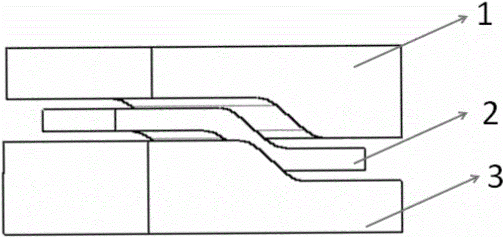
[0038]The invention is not only suitable for bar processing, but also can be used for plate processing. This embodiment takes plate processing, shearing and pressure deformation as an example to illustrate. For the mold equipment and plate forming results, see figure 1 , Figure 5 , Figure 6(a) and Figure 6(b). see figure 1 And Fig. 3 (a), this device is provided with upper mold 1, lower mold 3 and feeding mechanism, upper mold 1 is fixed with upper mold base, lower mold 3 is fixed with lower mold base, blank 2 is fixed with feeding mechanism, blank 2 It is located between the upper die 1 and the lower die 3; the corresponding surfaces of the upper die 1 and the lower die 3 and the blank 2 include: the upper flat section I6, the lower flat section II8, the curved section 7, and the upper flat section The transition between I6 and the flat section II8 at the lower part is connected by the curved section 7, the transition between the flat section I6 at the upper part and the ...

Embodiment 2

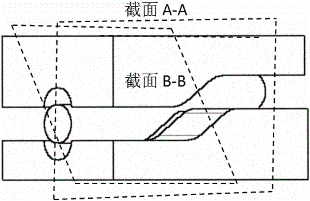
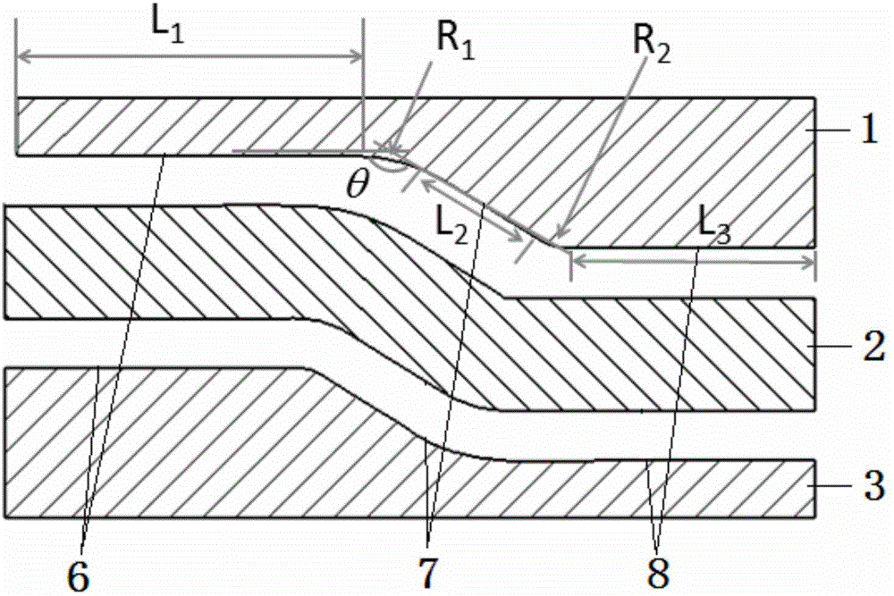
[0046] Such as figure 2 , Fig. 3 (a) and Fig. 3 (b), in the present embodiment 2, the bar compression-shear processing is also taken as an example to illustrate the basic process and principle of realizing the one-shear-two-compression stress state in the plate. The device is equipped with an upper mold 1, a lower mold 3 and a feeding mechanism. The upper mold 1 is fixed to the upper mold base, the lower mold 3 is fixed to the lower mold base, and the blank 2 is fixed to the feeding mechanism. The blank 2 is located between the upper mold 1 and the lower mold. Between 3; the corresponding surfaces of the upper die 1 and the lower die 3 and the blank 2 include: the upper flat section I6, the lower flat section II8, and the curved section 7, the upper flat section I6 and the lower flat section The transition between II8 is connected by the curved section 7, the rounded transition is adopted between the upper flat section I6 and the curved section 7, and the rounded transition i...

Embodiment 3

[0052] In this embodiment 3, the basic process and principle of realizing one-shear and three-compressive stress states are also described by taking plate compression-shear processing as an example, see Figure 4 . See Figure 3(a) and Figure 4 , the device is provided with an upper mold 1, a lower mold 3 and a feeding mechanism, the upper mold 1 is fixed to the upper mold base, the lower mold 3 is fixed to the lower mold base, the blank 2 is fixed to the feeding mechanism, and the blank 2 is located between the upper mold 1 and the lower mold base. Between the molds 3, the right side extrusion die 4 and the left side extrusion die 5 are arranged on both sides of the billet 2 respectively; the corresponding surfaces of the upper die 1 and the lower die 3 and the billet 2 respectively include: the flat section I6 located on the upper part, the The lower flat section II8 and curved section 7, the upper flat section I6 and the lower flat section II8 are connected and transitione...


PUM


Abstract

The invention relates to the technical field of plastic forming and particularly relates to a method and device capable of realizing continuous severe plastic deformation in different compression-shear composite strain paths. According to the method and the device, a bending die is designed so as to introduce uniform shear deformation into a material, and a variety of deformation states such as pure shearing, one-shearing-and-one-compressing, one-shearing-and-two-compressing and one-shearing-and-three-compressing can be conveniently realized in the material under the fit of compression of other directions. Furthermore, through the single-channel deformation of a multi-bent-section bending die or the multi-channel deformation of a single-bent-section bending die, the accumulation of the severe plastic deformation can be effectively realized. The method and the device can achieve the continuous deformation machining of metallic sheet and bar materials, and the prepared materials can have ultrafine-crystal and even local nanocrystal structures.

Description

technical field [0001] The invention relates to the technical field of plastic forming, in particular to a method and device capable of realizing continuous large plastic deformation under different compressive-shear composite strain paths. Background technique [0002] The large plastic deformation (SPD) processing technology is currently a commonly used plastic processing method for the preparation of high-performance metal materials and components. Compression-shear (referred to as compression-shear) composite deformation is a kind of SPD processing technology, which is often used to prepare materials with ultrafine crystals and even partial nanocrystals. During the forming process, shear deformation can effectively refine the grain structure and improve the performance of materials and components. Currently existing compression-shear processes mainly include high-pressure torsion (HPT), equal-channel extrusion (ECAP), rotary die extrusion (TE) and other processes, but t...

Claims


Application Information

Patent Timeline
IPC IPC(8): B21C25/08B21C23/06B21C23/08
CPCB21J1/025B21C25/08B21C23/06B21C23/08
Inventor 宋鸿武陈帅峰程明张士宏
Owner INST OF METAL RESEARCH - CHINESE ACAD OF SCI
Why Eureka
Try Eureka