
Ultrahigh-layer special-shaped steel pipe column assembly method

A special-shaped steel pipe and assembly method technology, which is applied in the direction of assembly machines, workbenches, metal processing equipment, etc., can solve the problems of low precision and large processing errors of super high-rise special-shaped steel pipe columns, and achieve the effect of reducing errors.

Active Publication Date: 2016-12-21
KOCEL STEEL STRUCTURE CO LTD
View PDF7 Cites 5 Cited by
  • Summary
  • Abstract
  • Description
  • Claims
  • Application Information

AI Technical Summary

Problems solved by technology

[0006] The purpose of the present invention is to provide a method for assembling super-high-rise special-shaped steel pipe columns to alleviate the technical problems of large processing errors and low precision of super-high-rise special-shaped steel pipe columns in the prior art

Method used


Image

  • Ultrahigh-layer special-shaped steel pipe column assembly method
  • Ultrahigh-layer special-shaped steel pipe column assembly method
  • Ultrahigh-layer special-shaped steel pipe column assembly method

Examples


Embodiment 1

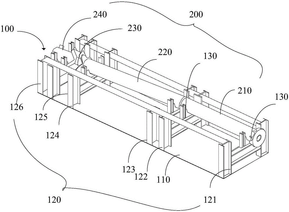
[0053] This embodiment provides a method for assembling a super-high-rise special-shaped steel pipe column, such as figure 1 , 3 shown, including the following steps:

[0054] S101, performing a three-dimensional modeling design on the tire frame 100 according to the size of the super-high-rise special-shaped steel pipe column 200;

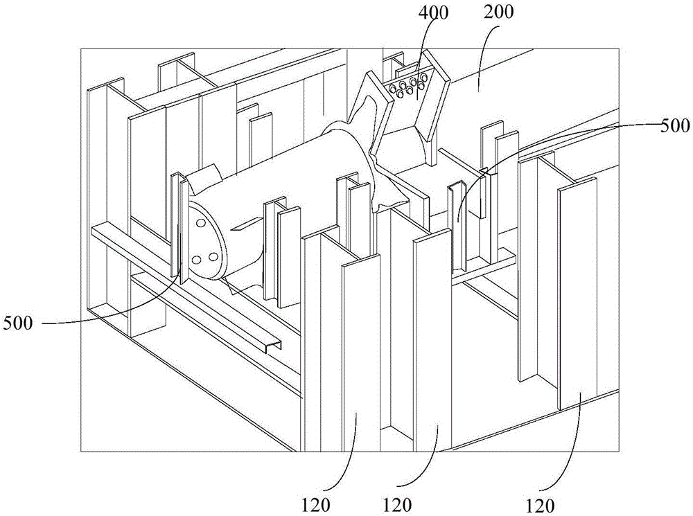
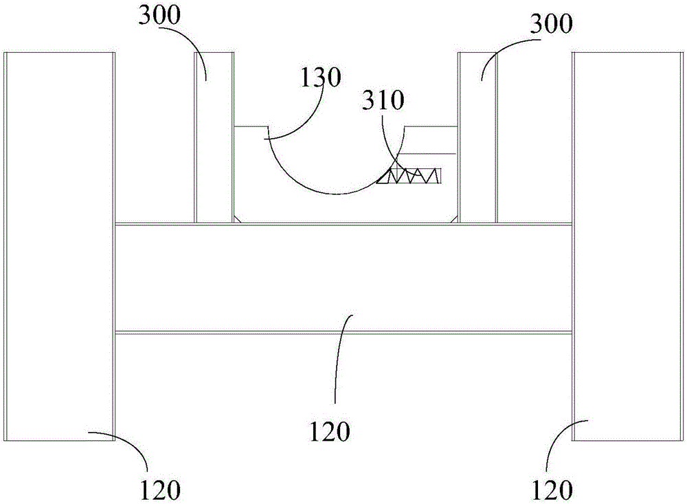
[0055]S102, prepare the tire frame 100, wherein the tire frame 100 includes a horizontal base 110, a fixed bracket 120 and a positioning plate 130, the fixed bracket 120 is located above the horizontal base 110; the side of the fixed bracket 120 away from the horizontal base 110 forms a limit groove; the inner side wall of the limit groove is provided with a positioning plate 130 to adjust the angle and orientation of the super-high-rise special-shaped steel pipe column 200;

[0056] S103 , assembling the super high-rise special-shaped steel pipe column 200 on the tire frame 100 .

[0057] The method for assembling a super-high-rise special-sha...

Embodiment 2

[0076] This embodiment provides a method for assembling super high-rise special-shaped steel pipe columns on the basis of the above-mentioned embodiments. During the assembly process of the above-mentioned super high-rise special-shaped steel pipe columns, there are also steps of detection and adjustment, as follows:

[0077] S201, in the tire frame preparation process, after the preparation of the horizontal base 110, the fixing bracket 120 and the positioning plate 130 needs to be tested, if the horizontal base 110, the fixing bracket 120 and the positioning plate 130 meet the design requirements, the horizontal base 110, fixed The bracket 120 and the positioning plate 130 are assembled.

[0078] The above-mentioned inspection process can screen out the parts that do not meet the standards, so as to ensure that the preparation of the tire frame meets the design requirements.

[0079] S202, during the preparation process of the tire frame 100, after the assembly of the horizo...


PUM


Abstract

The invention aims to provide a ultrahigh-layer special-shaped steel pipe column assembly method, and relates to the technical field of steel structure manufacturing. The method comprises the following steps: the three-dimensional modeling design is performed for a jig frame according to the size of a ultrahigh-layer special-shaped steel pipe column; the jig frame is prepared, and includes a horizontal base, a fixed bracket and a positioning plate; the fixed bracket is positioned on the horizontal base; a limiting groove is dig in one side, far from the horizontal base, of the fixed bracket; the positioning plate is arranged on the inner side wall of the limiting groove for adjusting the angle and the direction of the ultrahigh-layer special-shaped steel pipe column; and the ultrahigh-layer special-shaped steel pipe column is assembled on the jig frame. The method relieves the technical problems of high error and low precision in machining of the ultrahigh-layer special-shaped steel pipe column in the prior art.

Description

technical field [0001] The invention relates to the technical field of steel structure fabrication, in particular to a method for assembling a super high-rise special-shaped steel pipe column. Background technique [0002] With the development of the national construction industry and the application of various new construction technologies and materials, super high-rise building steel structures are widely used in large commercial office buildings, residential buildings, office buildings and ornamental tower high-rise buildings. The structural characteristics of super high-rise steel structure buildings are: light weight and high strength materials, good seismic performance and overall mechanical performance, flexible structural layout, and large space and large bay structures can be formed according to the functional requirements of the building. The super high-rise steel structure can also be designed into various shapes or special-shaped steel structures according to the...

Claims


Application Information

Patent Timeline
Patent Type & Authority Applications(China)
IPC IPC(8): B23P21/00B25H1/06
CPCB23P21/00B25H1/06
Inventor 黄戴春冯剑张昆陶雄壮罗正山刘永峰
Owner KOCEL STEEL STRUCTURE CO LTD
Learn More