Blade rest of slicing machine

A slicer and knife holder technology, which is applied in metal processing and other directions, can solve the problems that the knife holder has no protective structure, the blade is prone to accidents, finger scratches, etc., and achieves the effects of less accidents, easy removal, and convenient use

Active Publication Date: 2016-12-21
浙江省金华市科迪仪器设备有限公司
View PDF6 Cites 7 Cited by
  • Summary
  • Abstract
  • Description
  • Claims
  • Application Information

AI Technical Summary

Problems solved by technology

[0003] The blade is installed on the knife holder, and the position of the blade can be adjusted through the knife holder, but the existing knife holder has no protective structure, and it is easy to cause accidents in the non-working state or when disassembling the blade, and scratch your fingers

Method used


Image

  • Blade rest of slicing machine
  • Blade rest of slicing machine
  • Blade rest of slicing machine

Examples


Embodiment Construction

[0056] Below in conjunction with each accompanying drawing, the present invention is described in detail.

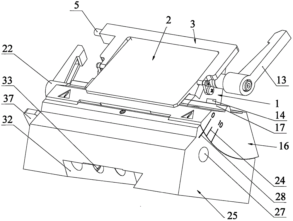
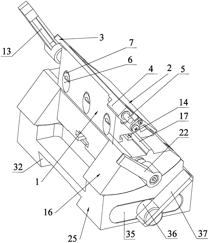
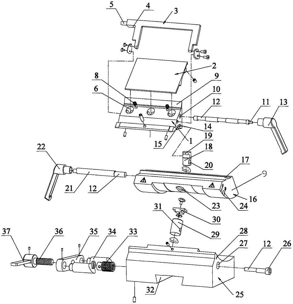
[0057] Such as figure 1 , 2 As shown in and 3, a knife holder of a slicer includes a mounting base 1 and a clip 2 that cooperates with the mounting base to clamp the blade, and also includes:

[0058]The turret 3 is rotatably mounted on the mounting base 1. The turret 1 has a first working position that is turned up to cover the blade, and a second working position that is turned down;

[0059] The unloading tool 5 is slidably arranged on the free end of the turret 3, and is used to cooperate with the blade when the turret is in the first working position, and push the blade out of the mounting seat;

[0060] The elastic piece is used to reset the knife unloading piece 5 .

[0061] Such as image 3 As shown, in this embodiment, the mounting seat 1 has a blade mounting surface 9, and the clip 2 cooperates with the blade mounting surface 9 for clamping the blade; and ...


PUM


Abstract

The invention discloses a blade rest of a slicing machine. The blade rest comprises a mounting seat, and a clamping piece which is matched with the mounting seat and used for clamping a blade. The blade rest further comprises a rotary rack, a blade dismounting piece and an elastic piece; the rotary rack is rotationally mounted on the mounting seat, and is provided with a first working position and a second working position; the rotary rack is turned upwards to be in the first working position to cover the blade, and is turned downwards to be in the second working position; the blade dismounting piece is slidingly arranged at the free end of the rotary rack, is used be matched with the blade and pushes the blade out of the mounting seat when the rotary rack is located in the first working position; and the elastic piece is used to allow the blade dismounting piece to be reset. With the adoption of the rotary rack, after slicing operation is finished, the rotary rack can be turned upwards to be in the first working position, by this time, the rotary rack can cover the blade, the blade can be prevented from scratching people and the blade can also be protected; with the design of the blade dismounting piece and the elastic piece, by pressing the blade dismounting piece, the blade dismounting piece moves to push the blade out of the mounting seat, so that manual taking-out is facilitated, and the possibility of accidents is low.

Description

technical field [0001] The invention relates to a slicer, in particular to a knife holder of the slicer. Background technique [0002] In the middle of the last century, with people's continuous understanding and research on diseases, in addition to diagnosing diseases from gross tissues with the naked eye, it is also necessary to diagnose diseases from tissue structure and cell changes, which requires biological tissues to be made into thin slices of about 5um. Observe under a microscope, thus producing a microtome of biological tissue, the biological tissue is set on the embedding frame by paraffin, then the embedding frame is installed on the chuck of the embedding frame, and sliced ​​by the blade. [0003] The blade is installed on the knife holder, and the position of the blade can be adjusted through the knife holder. However, the existing knife holder has no protective structure, and it is easy to cause accidents in the non-working state or when the blade is disassemb...

Claims


Application Information

Patent Timeline
Patent Type & Authority Applications(China)
IPC IPC(8): B26D7/26
CPCB26D7/2614
Inventor 江泽群董志荣
Owner 浙江省金华市科迪仪器设备有限公司
Why Eureka
Try Eureka