Four-column lifting structure for screen frame of screen printer machine

A lifting structure and screen printing machine technology, which is applied to screen printing machines, printing machines, rotary printing machines, etc., can solve the problems of unsatisfactory flatness of the screen frame, low accuracy of height positioning, and difficult control of the process. Improve the utilization rate of printing materials and printing quality, control the lifting process, and ease the lifting process

Active Publication Date: 2016-12-21
立川无锡半导体设备有限公司
View PDF11 Cites 6 Cited by
  • Summary
  • Abstract
  • Description
  • Claims
  • Application Information

AI Technical Summary

Problems solved by technology

[0002] The full name of the screen printing machine is "Screen Printer Machine". It is a device that prints solder paste or patch glue onto the PCB pad through a screen. It can be divided into vertical screen printing machine, oblique arm Screen printing machine, turntable screen printing machine, four-column screen printing machine and automatic screen printing machine are mainly used in the electronic processing industry, printed circuit board silk screen logo, instrument shell panel logo, solder paste printing in the process of circuit board processing, etc., printing When the plate is printed, the ink is transferred to the substrate through the holes of the stencil through a certain pressure to form images or characters. First, the silk fabric, synthetic fiber fabric or wire mesh is stretched on the screen frame, and the paint film is engraved by hand. Or photochemical plate-making method to make the printing plate, in order to ensure the quality of ink printing or character printing on the board surface, the stability of the screen plate is more stringent. The screen frame is an important component of the curved screen printing machine. In order to ensure the printing quality, generally The screen frame must be removed for cleaning at regular intervals, and replaced with a new screen frame. After the screen frame is reinstalled, the fixed position of the screen frame and the screen frame fixing frame deviates, so it is impossible to ensure that the printed pattern is on the receiving end. The correct position of the object affects the normal work. In order to adapt to different working conditions, the screen printing machine requires different heights. The screen frame of the traditional screen printing machine is adjusted by chain drive, but the chain structure is unstable and unsafe, and the process is difficult to control. The height The positioning accuracy is low, and the flatness of the screen frame cannot meet the requirements. The existing curved surface screen printing machine generally controls the left and right positions of the screen frame fixing frame through the induction fine-tuning switch, so as to realize the adjustment of the screen frame. However, the control range of this switch is only 1cm ~ 10cm, the adjustment range is limited, and the positioning accuracy is poor. The vibration of the screen printing machine during the production process will also cause the manual fixing screws to loosen, causing the screen to shift and cause batch quality problems.

Method used


Image

  • Four-column lifting structure for screen frame of screen printer machine

Examples


Embodiment Construction

[0013] The technical solutions in the embodiments of the present invention will be clearly and completely described below in conjunction with the accompanying drawings in the embodiments of the present invention. Obviously, the described embodiments are only some of the embodiments of the present invention, not all of them. Based on The embodiments of the present invention and all other embodiments obtained by persons of ordinary skill in the art without making creative efforts belong to the protection scope of the present invention.

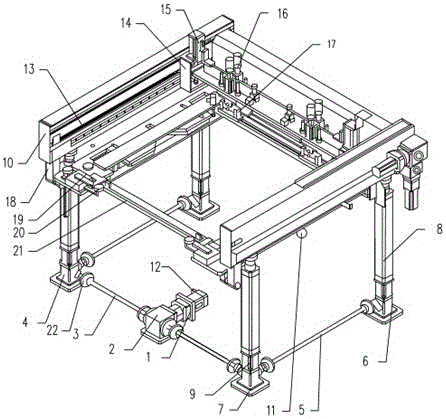
[0014] see figure 1 , a four-column lifting structure of a screen printing machine screen, including a servo motor 1, a cross diverter 2 is provided on one side of the servo motor 1, a first transmission rod 3 is provided on both sides of the cross diverter 2, and a first transmission rod 3 is provided on the first side of the servo motor 1 A gear at one end of a transmission rod 3 is connected to the first cross steering table 4, through the st...


PUM


Abstract

The invention relates to a four-column lifting structure for a screen frame of a screen printer machine and belongs to the technical field of screen printing auxiliary tools. The four-column lifting structure comprises a servo motor. A cross-shaped steering device is arranged at one side of the servo motor. The two sides of the cross-shaped steering device are each provided with a first transmission rod. A gear at one end of each first transmission rod is connected with a first cross-shaped steering platform. A gear at one side of each first cross-shaped steering platform is connected with a second transmission rod. One end of each second transmission rod is connected with a second cross-shaped steering platform. The bottom of each first cross-shaped steering platform and the bottom of each second cross-shaped steering platform are each provided with a base, and the top of each first cross-shaped steering platform and the top of each second cross-shaped steering platform are each provided with a ball screw electric cylinder. A tensioning coupling is arranged between each ball screw electric cylinder and the corresponding first cross-shaped steering platform as well as between each ball screw electric cylinder and the corresponding second cross-shaped steering platform. The screen frame is arranged at the tops of the ball screw electric cylinders. A gravity sensor is arranged at one side of the bottom of the screen frame. A control device is arranged at the other side of the servo motor and controls the extending-and-contracting value of each ball screw electric cylinder for location. The four-column lifting structure is high in locating precision, safe and reliable.

Description

technical field [0001] The invention relates to a screen printing machine screen frame four-column lifting structure, which belongs to the technical field of screen printing accessories. Background technique [0002] The full name of the screen printing machine is "Screen Printer Machine". It is a device that prints solder paste or patch glue onto the PCB pad through a screen. It can be divided into vertical screen printing machine, oblique arm Screen printing machine, turntable screen printing machine, four-column screen printing machine and automatic screen printing machine are mainly used in the electronic processing industry, printed circuit board silk screen logo, instrument shell panel logo, solder paste printing in the process of circuit board processing, etc., printing When the plate is printed, the ink is transferred to the substrate through the holes of the stencil through a certain pressure to form images or characters. First, the silk fabric, synthetic fiber fabr...

Claims


Application Information

Patent Timeline
Patent Type & Authority Applications(China)
IPC IPC(8): B41F15/34
CPCB41F15/34
Inventor 林邦羽
Owner 立川无锡半导体设备有限公司
Why Eureka
Try Eureka