
Thin film dividing and cutting machine with rolling shafts overturnable

A technology of rewinding and slitting machine, applied in the direction of winding strips, thin material processing, sending objects, etc., can solve the problems of reduced production efficiency, waste of raw materials, uneven collection of materials, etc., to improve production efficiency and avoid waste. Effect

Active Publication Date: 2016-12-21
江阴市科盛机械有限公司
View PDF11 Cites 19 Cited by
  • Summary
  • Abstract
  • Description
  • Claims
  • Application Information

AI Technical Summary

Problems solved by technology

[0004] 1. Existing slitting machines generally use upper and lower rewinding shafts to collect materials. When collecting materials, it is necessary to wait for all the materials on the two rewinding shafts to be collected and unload the finished materials before starting the next winding. Twice There is a waste of time between winding processes, resulting in increased working hours and reduced production efficiency
[0005] 2. Existing slitters generally use suspended winding rollers. Due to their own weight, the suspended winding rollers cannot accurately adjust the pressure during use, which may easily lead to uneven collection of materials.
[0006] 3. The circular knife device on the existing slitting machine needs to manually adjust the distance between the knife and the knife according to the demand, which is not only time-consuming, labor-intensive, labor-intensive, but also prone to deviation, resulting in slitting errors and waste of raw materials
[0007] 4. The unloading frame used for the existing slitting machine is generally a mechanical unloading frame. When unloading, it is necessary to manually push the unloading arm to turn, and the unloading arm can only rotate horizontally, which is not only time-consuming and laborious, but also unnecessary. Easy to pack materials

Method used


Image

  • Thin film dividing and cutting machine with rolling shafts overturnable
  • Thin film dividing and cutting machine with rolling shafts overturnable
  • Thin film dividing and cutting machine with rolling shafts overturnable

Examples


Embodiment Construction

[0030] A specific embodiment of the present invention will be described in detail with reference to the accompanying drawings, but the claims of the present invention are not limited in any way.

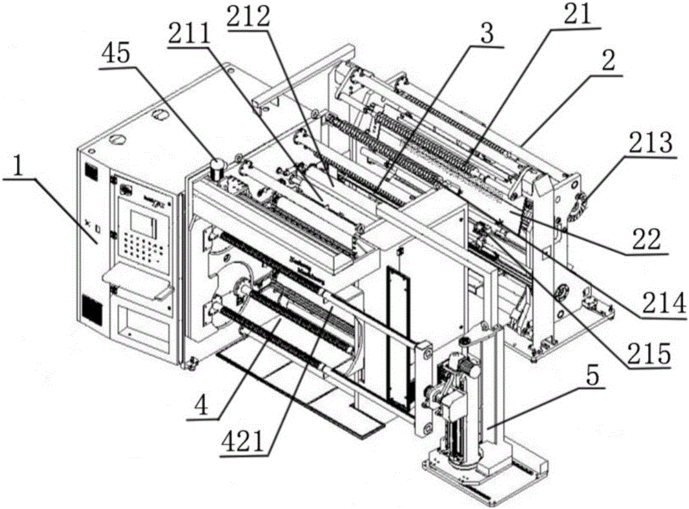
[0031] Such as figure 1 As shown, a rewinding film slitting machine includes a PLC control mechanism 1, an unwinding mechanism 2, a slitting mechanism 3, a winding mechanism 4 and an unloading mechanism 5, and the PLC control mechanism 1 is connected with the unwinding mechanism 2 and the dividing mechanism respectively. The cutting mechanism 3, the winding mechanism 4 and the unloading mechanism 5 are connected;

[0032] The unwinding mechanism 2 includes an unwinding motor, an unwinding transmission mechanism 21 and a material receiving platform 22, and the unwinding transmission mechanism 21 includes a main traction roller 211, a traction pressure roller 212, an unwinding brake 213, a guide roller 214 and a deviation correction controller 215;

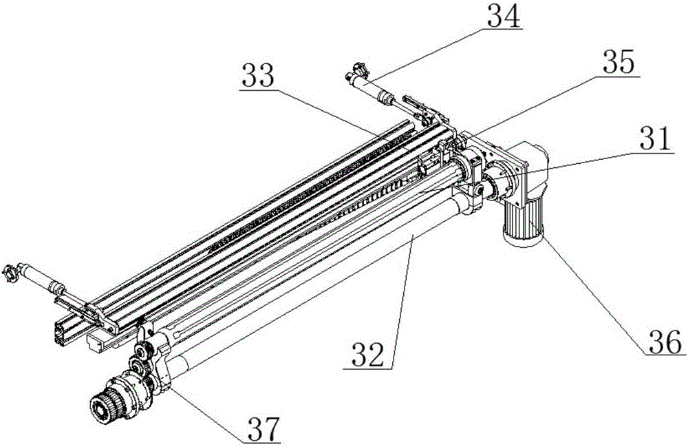
[0033] Such as figure 2 As shown...


PUM


Abstract

The invention relates to the field of dividing and cutting machines and discloses a thin film dividing and cutting machine with rolling shafts overturnable. The thin film dividing and cutting machine comprises a PLC control mechanism, an unrolling mechanism, a dividing and cutting mechanism, a rolling mechanism and a discharging mechanism. The PLC control mechanism is connected with the unrolling mechanism, the dividing and cutting mechanism, the rolling mechanism and the discharging mechanism. The unrolling mechanism comprises an unrolling motor, an unrolling transmission mechanism and a material receiving platform. The unrolling transmission mechanism comprises a main traction roller, a traction pressing roller, an unrolling brake, a guide roller and a deviation-rectifying controller. The rolling mechanism comprises a rolling motor, rolling transmission mechanisms, a rolling shaft overturning mechanism and the two or more rolling shafts. The rolling shaft overturning mechanism comprises rolling shaft overturning plates, a rolling shaft supporting plate, overturning plate air cylinders and rolling shaft air cylinders, wherein the overturning plate air cylinders are used for driving the rolling shaft overturning plates to be overturned and located, and the rolling shaft air cylinders are used for locating the rolling shafts. One end of each rolling shaft is connected with the corresponding rolling shaft overturning plate, and the other end of each rolling shaft is connected with the rolling shaft supporting plate. The thin film dividing and cutting machine has the beneficial effects that rolling efficiency is high; rolling is conducted neatly; and time and labor are saved in the discharging process.

Description

technical field [0001] The invention relates to the field of slitters, in particular to a film slitter with a reversible winding shaft. Background technique [0002] Slitting machine is a kind of mechanical equipment that cuts wide paper, mica tape or film into multiple narrow-width materials. It is often used in papermaking machinery, wire and cable mica tape, and printing and packaging machinery. [0003] Existing slitting machines for plastic film slitting have the following problems: [0004] 1. Existing slitting machines generally use upper and lower rewinding shafts to collect materials. When collecting materials, it is necessary to wait for all the materials on the two rewinding shafts to be collected and unload the finished materials before starting the next winding. Twice There is a waste of time between the winding processes, resulting in increased working hours for workers and reduced production efficiency. [0005] 2. Existing slitters generally use suspended w...

Claims


Application Information

Patent Timeline
Patent Type & Authority Applications(China)
IPC IPC(8): B65H35/02B65H18/10B65H18/26B65H19/30B65H16/06B65H23/032
CPCB65H16/06B65H18/10B65H18/26B65H19/30B65H23/032B65H35/02
Inventor 浦建科邱佩洪
Owner 江阴市科盛机械有限公司
Learn More