Prefabricated reinforced concrete component connecting method

A technology of reinforced concrete and precast concrete, which is applied in the direction of building structure and construction, can solve the problems of difficult to guarantee construction quality, difficult to guarantee grouting quality, and complicated construction process, so as to improve the connection performance of steel bars, improve the bonding performance, and facilitate construction. Effect

Inactive Publication Date: 2016-12-21
初明进
View PDF0 Cites 2 Cited by
  • Summary
  • Abstract
  • Description
  • Claims
  • Application Information

AI Technical Summary

Problems solved by technology

The connection nodes between components in the existing prefabricated concrete structure are generally the weak link of the structure, which affects the mechanical performance; at present, the reinforcement connection between the upper and lower prefabricated components of the prefabricated structure adopts the reinforcement sleeve grouting connection, the grout anchor connection, etc., the construction process Complex, construction quality is not easy to guarantee
[0003] The connection between existing prefabricated components is generally to reserve steel bars in the lower components and insert them into the upper components. For example, steel sleeve grouting connection, grout anchor connection and other technologies anchor the lower wall reinforcement in the upper wall. Grouting requires pressure. The quality of grouting is not easy to guarantee, and the construction is more complicated

Method used


Image

  • Prefabricated reinforced concrete component connecting method
  • Prefabricated reinforced concrete component connecting method
  • Prefabricated reinforced concrete component connecting method

Examples


Embodiment Construction

[0031] The method for connecting prefabricated reinforced concrete members of the present invention will be described in detail below with reference to the accompanying drawings and embodiments.

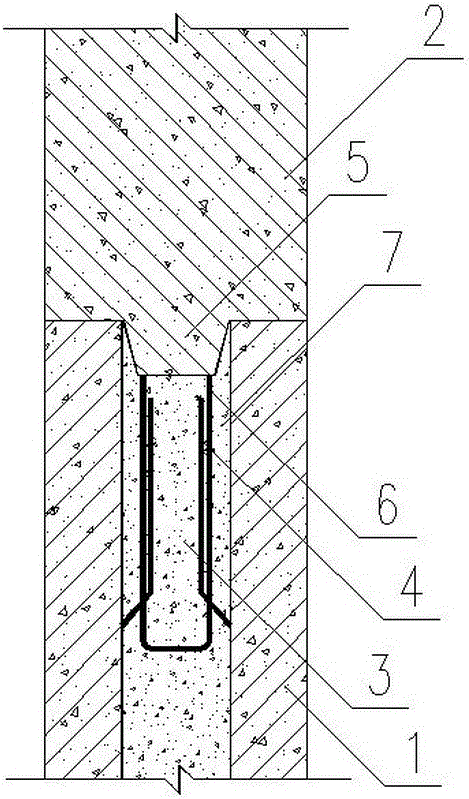
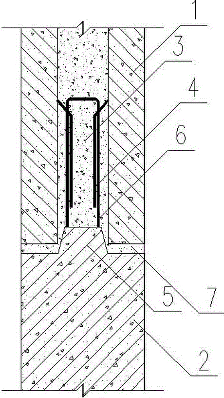
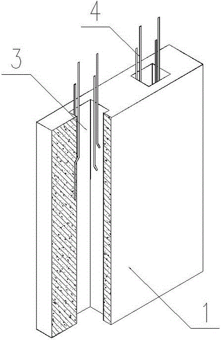
[0032] An embodiment of the method for connecting prefabricated reinforced concrete members proposed by the present invention, such as figure 1 or figure 2 or image 3 , the first prefabricated reinforced concrete component 1 is provided with at least one through hole 3 , a steel bar 4 is arranged in the hole 3 , and the steel bar 4 is anchored in the concrete on the side wall of the hole 3 . Concrete protrusions 5 are set on the second prefabricated reinforced concrete member 2, and anchoring steel bars 6 protrude from the protrusions 5; the first prefabricated reinforced concrete member 1 and the second prefabricated reinforced concrete member 2 are installed, and the second prefabricated reinforced concrete member 2 The protrusion 5 extends into the hole 3, and the anchoring st...


PUM


Abstract

The invention relates to a method for connecting prefabricated reinforced concrete members, belonging to the technical field of prefabricated concrete structures. The connection method connects the first prefabricated concrete member and the second prefabricated concrete member as a whole, and it is characterized in that at least one through hole is opened on the first prefabricated reinforced concrete member, and a steel bar is arranged in the hole, and the steel bar Anchored in the concrete of the side wall of the hole; there is a concrete protrusion on the second prefabricated reinforced concrete member, and the end of the protrusion extends out of the anchoring steel bar; the first prefabricated reinforced concrete member and the second prefabricated reinforced concrete member are installed, and the first prefabricated reinforced concrete member is installed. The protrusions of the two prefabricated reinforced concrete components are all or partially extended into the hole; between the first prefabricated reinforced concrete component and the second prefabricated reinforced concrete component, the hole is filled with concrete or grouting material.

Description

technical field [0001] The invention belongs to the technical field of prefabricated reinforced concrete structures and is suitable for assembling integral concrete structure systems. Background technique [0002] Prefabricated concrete structure is a structural form suitable for industrialization. The connection structure between prefabricated components in the assembled monolithic precast concrete structure determines the overall performance of the structure. The connection nodes between components in the existing prefabricated concrete structure are generally the weak link of the structure, which affects the mechanical performance; at present, the reinforcement connection between the upper and lower prefabricated components of the prefabricated structure adopts the reinforcement sleeve grouting connection, the grout anchor connection, etc., the construction process Complex, construction quality is not easy to guarantee. [0003] The connection between existing prefabric...

Claims


Application Information

Patent Timeline
Patent Type & Authority Applications(China)
IPC IPC(8): E04B1/41
CPCE04B1/41
Inventor 初明进
Owner 初明进
Why Eureka
Try Eureka